1Doctor Of Philosophy Of Technical Sciences, Faculty Of Engineering, Civil Engineering Department, Urmia Branch, Islamic Azad University, Urmia, Iran
2Ph.D. Student Of Civil Engineering-Structure, Faculty Of Engineering, Civil Engineering Department, Urmia Branch, Islamic Azad University, Urmia, Iran
Corresponding author Email: ashkan72@rambler.ru
Article Publishing History
Received: 12/09/2018
Accepted After Revision: 19/11/2018
In this article environmental behavior of steel beams embedded in concrete under static loads was investigated. The obtained experimental results were compared for precision of the sample configuration of a three-dimensional finite element model. In this study, for modeling concrete, Concrete Damaged Plasticity was used. The analytical method used in this study for explicit nonlinear dynamic analysis Dynamic Explicit is selected. In contrast, in samples with a ratio of 0.5 steel flange width, usually bending failure were observed.
Mixed Beams, Flexural Behavior, Static Loading, Finite Element Method.
Bandehlou A. K, Soltanabadi R. S. Enviromental Behavior of Steel Beams Embedded in Concrete Under Static Loads. Biosc.Biotech.Res.Comm. 2018;11(4).
Bandehlou A. K, Soltanabadi R. S. Enviromental Behavior of Steel Beams Embedded in Concrete Under Static Loads. Biosc.Biotech.Res.Comm. 2018;11(4). Available from: https://bit.ly/2m8bm9R
Introduction
Analytical studies were conducted, including the members of the Security, by Spacone and El-Tawilin 2004. In this study, nonlinear analysis steel-concrete composite structures were investigated. Another study by Camps et al., (2017) has analyzed flexural behavior of composite beams with deformable connection. How the tensions in the interface of concrete and steel sections and increase ductility and impact assessed concrete creep and shrinkage behavior of the composite was investigated. Another study evaluated the short beam strength composite columns by Mirza and Skranek which was conducted in 1991. Other research studies on prestressed beams have been combined in this research, which are based on analytically studied proposals for the design of this type of beam bending is presented, (Zhao and Li 2017).
The survey in 1989 was conducted by Saadatmanesh and colleagues. The use of prestressed steel beams for composite steel – concrete increases the bearing capacity of steel beams to the current stage and also increases the resistance of the composite section final. At the same time prestressing tension flange reduced the amplitude cyclic stress and improve fatigue resistance.In another study conducted in 2005 by Ellbody and Young, shear bond strength impact and efficiency in composite beams has been investigated. Another study under the title of ultimate strength of continuous composite beams under combined bending and cutting was done by Liang et al. Based on numerical results, a new design model based on vertical shear resistance and interaction Anchor – cutting the continuous composite beams have been proposed. The proposed design models were compared with experimental results and good agreement is shown (Goldston, et al. 2016 and Ongpenget al.2018).
Zhao and Li in 2008, conducted a numerical study in conjunction with a new way to create continuity in composite beams. The flow of steel beam to reduce the local rigidity and lead to brittle fracture the concrete. In 2005, Lam and his colleagues evaluated the behavior of shear connectors for composite beams was conducted stud.
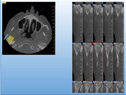 |
Figure 1: Change Chart bearing capacity by changing the size of the mesh |
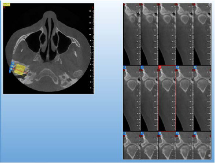 |
Figure 2: Change graph analysis time by changing the size of the mesh |
In this study, a model of efficient numerical simulation using the finite element method for laying out tests have been proposed. The model was validated against experimental results and with common standards such as BS5950 and the information given in EC4 and AISC were compared. By a number of researchers based on laboratory analysis and numerical research has been done on shear connectors, length, maximum width of cracks in concrete was found to be reduced. Lam and colleagues in 2005 studied pull tests on 12 samples of pre-fabricated hollow concrete slab, the scale is complete. In another work by Lam and El-Lobody (2005) new work has been developed to FEM modeling computational which has been obtained from experimental results which have been discussed in terms of accuracy. Comparison has been made on the conducted data and the results show good correlation between the finite element model from environmental point of view. In this study, the flexural behavior of steel beams embedded in concrete under static loads is investigated for sustainable environmental development.
Statement Of The Problem
Full of strength, using techniques to enhance the capacity of these members is very important. Capacity is up against loads of material to be used simultaneously and efficiently.
Modelingalman Limit For Constituents Mercury Compound
In this article for a sample configuration of a three-dimensional finite element model is used. For concrete modeling of three-dimensional elements (C3D8R) that an 8-node elements with reduced integration is used. Similar elements are considered for modeling steel sections. For longitudinal reinforcement and stirrups of the beam elements (B31) is used.
Concrete In Abaqus Finite Element Method
In this study, the method used for modeling concrete, Concrete Damaged Plasticity is the model. This model is based on the assumption of isotropic damage survey and design for use in concrete under different environmentalloading conditions and the desired effect was accomplished. The embedded model is used for reinforcement.
Load And Boundary Conditions
In the modeling study of rigid plates with a width of 10 cm was used as loading pages. Pages load and anchor tie in place by indicating that they have been fixed. Anchor plates on the boundary conditions with zero degrees of freedom U1 and U2 and UR2 and UR3 have taken place.
Meshed Model
Analysis of each of these models were calculated. By comparing the maximum load capacity for different meshing, percentage differences obtained for meshing with meshing elements smaller than 5 cm, less than 42/2 percent is obtained. That’s why the next 5 inches as the maximum size for meshing elements have been selected.
Extrusion method used to create pieces of concrete and steel beam is therefore for the mesh generator parts Swept meshing techniques are used. Elements used in the mesh of hexagonal Hex been selected. Seeded maximum size of 5 cm is selected and used to control the curvature maximum deviation factor by default, the software is intended to 1/0. In Figure 3 meshed model for one of the samples shown.
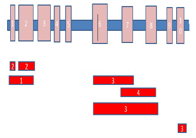 |
Figure 3: For an example of meshing in finite element software |
Analysis Model
Given the magnitude of the displacement and the need for non-linear analysis, dynamic methods for the analysis of selected models. The analytical method used in this study for explicit nonlinear dynamic analysis Dynamic Explicit is selected.
The Impact Of Changing The Entire Width Of The Beam Flange Width
Steel Tools
One of the important parameters influencing the behavior of the composite beams of steel embedded in concrete, steel and concrete beam cross section Dimensions. the probability of failure is compounded in July.
Is. For this purpose, five different models, including models with wing width ratios C1, C2, C3, C4 and C5 respectively steel with cross-sections of 120, 150, 180, 210 and 240 cm are selected.
All models have cross-sectional dimensions of 300 × 500 mm, respectively. Longitudinal bars diameter 19 mm and diameter of 10 mm are inadequate. The distance of each other 150 mm is considered inadequate and has not been used in any of these models is cutting.
Graphs Time – Displacement
Bar graphs – C1 to C5 models displacement is presented in Figure 4. As the charts once – movement can be observed with increasing steel flange width, capacity, as well as the final beam forming compound has increased. Figure 5 shows the curve of the ultimate capacity models. According to this chart, the increase in capacity of 22.3% for the C2 than C1 models, for models from C3 to C1 model 37/16%, 91/23% and times for the C4 to C1 model to model C5 to C1 models from 94/37% is obtained.
 |
Figure 4: Bar chart – midspan displacement for models C1, C2, C3, C4 and C5 |
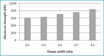 |
Figure 5: The graph ultimate bearing capacity for models C1, C2, C3, C4 and C5 |
 |
Figure 6: Contour stretch injury model C1 |
 |
Figure 7: Contour stretch injury model C2 |
 |
Figure 8: Injury contour drawing model C3 |
Tensile Contours Injury
In the form of (6) to (10) C1 to C5 models tensile injury contours are provided. With a little care can be noted that in models with smaller steel flange width, propagation of cracks at midspan is more considerable.
 |
Figure 9: Injury contour drawing model C4 |
 |
Figure 10: Contour injury tensile C5 model |
 |
Figure 11: Contour relative deformation Plastic Model C1 |
 |
Figure 12: Contour relative deformation Plastic Model C2 |
Reshape The Contours Of Plastic
Stickers (11) to (15) of plastic deformation contours C1 to C5 models for the show. three models have been predicted failure for shear.
In Table 1. The results of the analysis and prediction models include the strength of the type of failure is presented. The finite element analysis results in compliance with Regulation Iran relations have been evaluated. According to a survey made very good match between the results of finite element analysis of the samples and relations are provided in the bylaws. The ultimate shear capacity of 353.8 kN point in the relations of the Regulations is obtained. We see that in the C1 and C2 maximum shear force obtained from finite element analysis section is smaller than the shear capacity. Therefore, the models are broken due to reach its ultimate flexural capacity. Finite element analysis of bending failure for these models is the result. The results of finite element analysis also shows shear failure for these models.
 |
Figure 13: Contour relative deformation Plastic Model C3 |
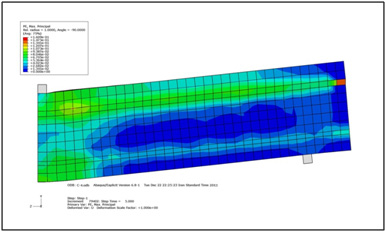 |
Figure 14: Contour relative deformation Plastic Model C4 |
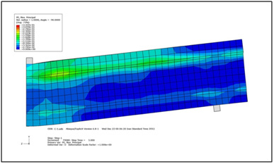 |
Figure 15: Contour relative deformation Plastic Model C5 |
| Table 1: Resistance and failure mode of composite beams with steel flange width ratios of | |||||
| Model | Width steel | Width ratio | Resistance models | The type of fracture | |
| V (KN) | M (KN m) | ||||
| C1 | 120 | 0.4 | 306.5 | 459.8 | Bending |
| C2 | 150 | 0.5 | 316.4 | 474.6 | Bending |
| C3 | 180 | 0.6 | 356.7 | 535.1 | Bending |
| C4 | 210 | 0.7 | 379.8 | 569.7 | Bending |
| C5 | 240 | 0.8 | 422.8 | 634.2 | Bending |
Conclusion
In this article Environmental behavior of steel beams embedded in concrete under static loads were investigated. In contrast, in samples with a ratio of 0.5 steel flange width, usually bending failure have been observed. Results demonstrated that by optimizing the static load in the process of the production, the environmental side effects will be reduced and can be efficient in clean concrete production.
References
Camps, B.; Baktheer, A.; Hegger, J.; Chudoba, R (2018). Experimental Characterization of Bond Fatigue Using Beam-End Tests with Push-In Loading. Proceedings 2, 417.
Ellobody, E. and Young, B. (2005) Performance of shear connection in composite beams with profiled steel sheeting,” Department of Structural Engineering, Faculty of Engineering, Tanta University, Tanta, Egypt, Journal of Hydraulic Engineering, ASCE, Vol.132, No. 9, pp.971-982
Goldston, Matt & Remennikov, Alex & Sheikh, Md. (2016). Experimental Investigation of the Behaviour of Concrete Beams Reinforced with GFRP Bars under Static and Impact Loading. Engineering Structures. 113. 220-232. 10.1016/j.engstruct.2016.01.044.
Lam, D., El-Lobody, E. (2005) Behavior of Headed Stud Shear Connectors in Composite Beam School of Civil Engineering, University of Leeds, U.K., Journal of StructuralEngineering, Vol.131, No.1, pp. 96-107, 2005.
Liang, Q.Q., Uy, B., Bradford, A., and Ronagh, H.R. (2003) Ultimate strength of continuous composite beams in combined bending and shear, School of Civil and Environmental Engineering, The University of New South Wales, Sydney, Australia, Journal of Structural Engineering, Vol.131, No.10, pp.1593-1600
Mirza, S.A., Skrabek, B.W. (1991) Reliability of Short Composite Beam-Column Strength Interaction,” Department of Civil Engineering, University of Lakehead, Canada, Journal of Structural Engineering, Vol.117, No.8, pp.2320-2339
Nardin, S.D., El Debs, L.H.C. (2009) Study of partially encased composite beams with innovative position of stud bolts, Department of Structural Engineering, University of Sao Paulo at Sao Carlos, Sao Carlos, Brazil, Journal of Constructional Steel Research, Vol.65, No.2, pp.342-350
Ongpeng, J. M. C., Oreta, A. W. C., & Hirose, S. (2018). Investigation on the Sensitivity of Ultrasonic Test Applied to Reinforced Concrete Beams Using Neural Network. Applied Sciences, 8(3), 405.
Saadatmanesh, H., Albrecht, P., Ayyub, B.M. (1989) Guidelines for Flexural Design of Prestressed Composite Beams Civil. Engrg.andEngrg. Mech., University of Arizona, Journal of Structural Engineering, Vol.115, No.11, pp.2944-2961
Spacone, E., El-Tawil, S. (2004) Nonlinear Analysis of Steel-Concrete Composite Structures Department of Civil Engineering, Department of Civil Engineering, University of Colorado, Journal of Structural Engineering, Vol.31, No.2, pp.523-533, 2004.
Zhao, G., Li, A. (2017) Numerical study of a bonded steel and concrete composite beam Laboratory of Mechanics, Materials and Structures, University of Reims Champagne Ardenne, France, Journal of Structural Engineering, Vol.86, No.19-20, pp.1830-