1DDS, MS, Assistant Professor, Department of Prosthodontics, School of Dentistry, Hamadan University of Medical Sciences, Hamedan, Iran
2DDS, MS, Assistant Professor, Department of Prosthodontics, School of Dentistry, Shahid Beheshti University of Medical Sciences, Evin, Tehran, Iran
3DDS, MS, Assistant Professor, Department of Orthodontics, School of Dentistry, Hamadan University of Medical Sciences, Hamedan, Iran
4*DDS, MS, Assistant Professor, Department of Prosthodontics, School of Dentistry, Hamadan University of Medical Sciences, Hamedan, Iran
Corresponding author Email: sarakhazaei_83@yahoo.com
Article Publishing History
Received: 29/06/2017
Accepted After Revision: 19/09/2017
The aim of this study was to assess the effect of dynamic loading and abutment type on removal torque value. Thirty-two analogs of fixtures with internal taper connections were divided into two groups of 16. The one-piece (OP) group received solid (one-piece) abutments and the two-piece (TP) group received two-piece abutments. Each group was further subdivided into subgroups C (control) without mechanical loading and T (test) with mechanical loading. The screw of abutments in OPC and TPC groups, were tighten and then removed to record the removal torque value (RTV). In OPT and TPT groups, abutments were tighten, mechanically loaded (300,000 cycles), removed, and the RTV were recorded. Two-way ANOVA and Tukey’s HSD post-hoc testwere used for data analysis.The significance threshold was set at 0.05. The mean torque loss of OPC group was significantly lower than both TPC and OPT groups (P < 0.05). But there was not significant different in torque lossvalues between abutments in TPC and TPT groups.Under mechanical loading, theremoval torque of both one-piece and two-piece groups decreased and this reduction was only significant for one-piece group. Also, the abutment type has significant effect on removal torque value.
Torque, Dental Abutment, Cyclic Loading
Firouz F, Heidari B, Alijani S, Khazaei S. Effect of Dynamic Loading on Removal Torque Value of One-Piece and Two-Piece Abutments. Biosc.Biotech.Res.Comm. 2017;10(3).
Firouz F, Heidari B, Alijani S, Khazaei S. Effect of Dynamic Loading on Removal Torque Value of One-Piece and Two-Piece Abutments. Biosc.Biotech.Res.Comm. 2017;10(3). Available from: https://bit.ly/2LaEY15
Introduction
Failure and complications with implant-supported prostheses still occur, despite the high clinical success rates in long-term. These complications include biological and mechanical problems. Screw loosening is the most commonly reported mechanical complication for single implant-supported prostheses. Different factors may contribute to loss or decrease in abutment screw torque such as fatigue, inappropriate tightening torque, failure in screw retightening after initial placement, settling effect, vibrating micro movements and excessive bending. The misfit of abutment or implant-supported crown, occlusal loading and structural design of implant connection are among other factors playing a role in this respect (Norton (1997, Jörnéus et al., 1992, Coelho et al., 2007 De Boever et al., 2006, Theoharidou et al., 2008).
The implant-abutment interface design can be roughly divided into two groups namely (I) butt-joints or slip fit joints with a passive fit and (II) conical interface with frictional fit between mating surfaces of abutment-implant complex; the latter type of interface also known as locking or Mores taper connection. In most previous studies, internal taper connections showed superior performance and were thought to minimize screw loosening and fracture, which commonly occur external hexagon butt-joint connections. An internal tapered abutment, based on the specific system used, may be attached to implant body by an external screw, orwith threads machined directly on the abutment body itself, which are calledone-piece (solid abutment) and two-piece abutments, respectively, (Finger et al., 2003 Budynas et al., 2008, Hansson 2000, Dittmer et al., 2011, Ricciardi et al., 2009, Cehreli et al., 2004 Aguirrebeitia et al., 2013 Rabelo et al., 2015).
It has been proven that both types are highly resistant to fatigue under dynamic loads and could function without any mechanical problems. One concern regarding the internal taper connection system is the possibility of cold welding of the abutment inside the implant. This was also mentioned by Sutter et al; whereas, other authors concluded that cold welding is presumably neutralized by a phenomenon called embedment relaxation. Clinically, it seems that One-piece abutments may be removed from the fixture more easily than two piece abutments, due to the nature of their design,which may causeless problems during removal, (Bozkaya et al., 1995, Weiss et al., 2000, Pintinha et al., 2013, Rabelo et al., 2015).
As mentioned earlier, screw loosening is the most common complication in single implant -supported restorations. This is important, particularly, incemented prosthesis, in which loosening or fracture of the abutment screw may lead to failure of prosthesis. Therefore, this study aimed to evaluate the effect of dynamic loading on removal torque value (RTV) of two types of internal taperabutments namely one-piece and two-piece abutments. The null hypothesis was that the RTV of one-piece and two-piece abutments would not decrease under dynamic loading.
Materials and Methods
In this in vitro experimental study, 32 analogs of fixtures (Ø 4.8 mm* 10 mm L, Simple line II, Dentium, Korea) with internal taper hexagon were chosen. In addition, 32 abutments (11-degree taper, Ø 4.5 mm* 5.5 mm L, Simple line II, Dentium, Korea) of two different types (one-piece and two-pieces) were used. Each analog was mounted in a mold containing auto-polymerizing acrylic resin.The customized molds were fabricated from brass and measured 20 mm in height and 25 mm indiameter, in addition, their upper surfaces were cut so that this surface had 30˚ angle relative to the horizontal plane. Then, on the upper ramp, ahole was drilled perpendicular to the surface for placement of implant analog (Figure 1). This design of the mold allowed for the fatigue tester to apply load to the abutment at a 30 ° angle relative to the long axis. A wooden jig was used for correct positioning of the molds on the surveyor. The jig was a ramp with a 60 ˚ angle relative to the horizontal plane. Therefore, by assembling the mold on the jig its upper surface was positioned parallel to the horizon. Next, analogs were placed inside the hole perpendicular to the ramp of mold using a surveyor. The hole was filled with auto-polymerizing acrylic resin in doughy stage right before analog insertion (Figure 2). Then, analogs were divided into two groups according to the type of abutment they would receive. The study groups were as follows:
OPC group: One-piece abutments that were not subjected to dynamic loading (control group, n=8).
TPC group: Two-piece abutments that were not subjected to dynamic loading (control group, n=8).
OPT group: One-piece abutments that were subjected to dynamic loading (test group, n=8).
TPT group: Two-piece abutments that were subjected to dynamic loading (test group, n=8).
 |
Figure 1: Brass mold |
 |
Figure 2: Wooden jig for correct positioning of molds on the surveyor |
To measure the tightening and removal torques, a digital torque meter (TQ-8800; Lutron electronic, Taiwan) with an accuracy of precision of 0.1 Ncm was used. Torque meter was positioned on top of a torque delivery device and the cylinder-analog-abutment assembly was fixed into a socket at the bottom of the device.
Before screw tightening, all abutments were lubricated with artificial saliva (Saliva Substitute; Roxane Laboratory Inc, USA). Then, all abutments in the control groups were tightened to 35 Ncm torque. After a 10-minute interval, abutments were retightened to the same torque to compensate for the loss of preload due to settling of surface at the interface. Ten minutes later, the RTV of abutments in the control groups was measured and recorded. For the test groups, 16 ceramic copings (e.max*Zir CAD, ivoclarvivodent) were fabricated with the same size and shape by computer aided design/computer aided manufacturing (CAD/CAM) technology (Sirona in Lab MCXL, Germany).
Since these abutments were cement-retained, for measurement of the RTV, the copings had to be removed from the abutment. For this reason, the coping were designed such that they had a hole in place of the abutment screw. Therefore, we hada direct accessto the coping hole, and there was no need to remove the crown after loading. Then, the adaptation of copings was verified and confirmed using light body silicone (Speedex, condensation polysiloxane, low consistency, Colten, Switzerland).
In the test groups, as well as the control groups, the abutments were torqued to 35 Ncmby digital torque meter in two cycles with 10-minutes intervals. Then, the crowns were placed on the abutments and cemented by a temporary cement (Temp bond, Kerr, Italy). During the experiment, the hole of crown was covered with composite. Afterward, each assembly of mold-analog-abutment-cap from the test groups was mounted and fixed to the electromechanical fatigue testing machine (CS-4, SDM echatronik, Germany) (Figure 3). The device has two lever arms that simultaneously apply force. The arm of device was so that the force was applied to the upper most part of the coping (Figure 4).
 |
Figure 3: Dynamic fatigue tester |
 |
Figure 4: Ceramic coping and position of applying force |
The fatigue tester was calibrated so that the lever arm soperated for 300,000 cycles (nearly corresponding toone year of chewing function) at a speed of 1Hz (60 rpm) [19].the position of load was Oblique load (withan angle of 30˚) of 100±5N was applied to each coping [19]. After each test, the specimens were transferred to the torque delivery device and the RTV was measured and recorded. The following formula was used to calculate the percentage of torque loss (Per tl):
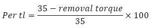
SPSS software version 21 was used for statistical analysis. The Per tl were statistically analyzed by Two-way ANOVA and Tukey’s HSD post-hoc test. The significance threshold was set at 0.05.
Results And Discussion
None of the tested samples showed abutment or screw fracture; there was no sign of crown loosening either after loading. Two-way ANOVA indicated that abutment types, dynamic loadingand their interaction had significant effects (P<0.05) on Percentage of torque loss. Table 1 shows the mean and standard deviations of Pertl inall study groups. There moval torque of abutments decreased in both groups (control and test group). TheOPC group presented the lowest torque loss. The highest torque loss was observed in OPT group. Pair wise comparisons of Pertl were then performed with Tukey’s HSD post-hoc test (Table 2). The mean Pertl in abutments of OPC group was significantly lower than that in TPC and OPT groups (P<0.05). Also, the difference between OPT and TPT groups was significant (P<0.05), But there was no significant different in Per tl of abutments between TPC and TPT groups (P>0.05). In our study, all abutments in both control and test groups showed reduction in removal torque value compared to the insertion torque. Thisindicated that no cold welding occurred in any implant-abutment interface, which was consistent with the results of previous studies (Norton 1999, Ricciardi et al, 2009 Pintinha et al., 2013, Kim et al 2014).
| Table 1: Mean and standard deviation of per tl for all groups (n=8) | |||||
| Group | N | Mean±standard deviation | 95% confidence interval for the mean
Lower boundUpper bound |
P value | |
| OPC | 8 | 8.93±4.76 | 4.9533 | 12.9167 | .000 |
| OPT | 8 | 51.02 ±4.61 | 47.1711 | 54.8839 | |
| TPC | 8 | 22.8±8.00 | 16.1642 | 29.5408 | |
| TPT | 8 | 23.2± 8.97 | 15.8487 | 30.5538 | |
| Table 2: Results of Tukey’s HSD post-hoc test for pairwise comparisonsper tl | ||||
| Mean Difference (I-J) | 95% Confidence Interval | |||
| Lower Bound | Upper Bound | P value | ||
| OPC& OPT | -42.092* | -51.3843 | -32.8007 | .000 |
| OPC&TPC | -13.917* | -23.2093 | -4.6257 | .002 |
| OPC&TPT | -14.266* | -23.5581 | -4.9744 | .001 |
| OPT&TPC | 28.175* | 18.8832 | 37.4668 | .000 |
| OPT&TPT | 27.826* | 18.5344 | 37.1181 | .000 |
| TPC&TPT | -0.34875 | -8.9431 | 9.6406 | 1.000 |
| *The mean difference is significant at the 0.05 level. | ||||
Norton showed that cold welding occurs only at the highest level of torque, right before the component failure and when plastic deformation is expected. In addition, cold welding does not occurin clinical levels of torque, and the removal torque is expected to be 10 to 20 % less than the initial torque. However, Sutter and colleagues stated that following torque application, the removal torque increases from 10 to 15 % compared to the initial torque in internal taper connections. They argued that probably, the effect of axial component of the simulated occlusal force surpasses other oblique and tensile forces that interact negatively with retention of abutments. But, other authors have reported different results, indicating that the cold welding, if occurs, is compensated by the settling effect, (Ricciardi et al., 2009 Cehreli et al., 2004).
The results from One-piece abutments showed that the mean torque loss Inthe test group was significantly higher than that in control group (8.93% in the control and 51.02 % in the test group). In One-piece systems, abutment serves asa screw; therefore, in the test group, with application of dynamic load, these forcesare directly transferred to the threads and decrease the removal torque. In addition, the bending and tensile stresses are produced at the interface andlead to greater reduction oftorque. The results of a previous study showed various ranges of torque loss in One-piece abutments. Pinhata et al. reported the mean torque loss values of 18.35% for the control group and 15% for the test group, Pintinha et al. (2013). This value was between 15 and 20% in the study by Norton et al. and between 10.5 and 5.4% in the study by Ricciardi et al. (2013).
A mean torque reduction of 8% by Cehreli et al. (2004) and 25% by Seol et al. (2015) has been reported in test groups. Different results of studies can partly be related to differences in the types of implant systems used. In addition, differences in experimental conditions should be considered. There are significant differences between our study and others in number of cycles, intensity, position, angle and rate of applied force. In two-piece abutments, the difference between the control (with 22.8% torque loss) and test group (with 23.2% torque loss) was not statistically significant.
Pinhata et al. (2013) reported a mean torque loss of 36% and 40.85% for the control and test groups, respectively. Similarly, Ricciardi et al. 2013 found the mean values of 32% forthe control group and 37.2% for the test group.Also, Seol et al. (2015) reported a mean torque loss of 48% for test group.Based on the results of our study, in the control groups, one-piece abutments showed significantly higher removal torque value than two-pieceabutments. When opening one-piece abutments, the retention caused by the tapered part of the abutment as well as retention caused by the threads should be overcome. But intwo-piece abutments, the removal torque recorded by torque meter is mainly spent to overcome the retention friction generated by the threads because in two-piece abutments, the abutment screw passes through the abutment andat the time of opening, this unit is removed from the abutment.Therefore, in these types of abutments, a large amount of torque required by the tapered part of the abutment is not registered by the torque meter (particularly inabutments that have anti-rotation feature). Thus, it seems logical that two-piece abutments show less removal torque than one-piece abutments.
After applying force, the torque loss of one-piece abutments was significantly higher than that of two-piece abutments. In two-piece abutments, since the screw and abutment are in two distinct parts (yet related), smaller amount of force exerted on the abutment is transferred to thescrew; whereas, in one-piece abutments, as mentioned earlier, the abutment serves as a screw and transfers dynamic forces directly to the threads and decreases the required removal torque.
In this study, we tried to establish conditions to simulate clinical masticatory conditions. Each sample under went 300,000 cycles of dynamic force, which corresponded to one year of normal chewing function. Inaddition, the abutments were lubricated by artificial saliva before applying torque because it has been suggested that greater initial preload can be achieved underwet conditions, Jaarda et al., (1993). Siamos et al., 2002 Lee et al., 2002, Winkler et al., 2003)
Applying proper torque recommended by the manufacturer is very important to prevent screw loosening and screw fracture. Jaarda et al. reported 15 to 48% error when closing the abutment screw by hand. Therefore, the abutments were tightened to 35 Ncm torque by a digital torque meter. Ten minutes later, the same torque was applied to compensate the loss of preload due to settling effect. Siamos et al. suggested that in order tominimize the loss of preload caused by the settling effect, the initial torque should beapplied again 10 minutes after initial tightening torque, (Siamos et al., 2002).
Considering the fact that biteforce actually acts on the super structure, it was appropriate to perform anexperiment in which dynamic forces are applied on the abutment after cementation of crown. Before cementation, precise and passive fit of caps was assessed by light-body silicon. Prostheses with active fit or improper adaptation can exertun desirable forces on the abutment, (Lee et al. 2002).
The limitations of this study included small sample size and short-term loading. In addition, our study had an in vitro design and had the limitation of in vitro studies in simulating the complex nature of mastication cycles. In the oral environment, forces are applied in different directions and angles to the axis of abutments; moreover, the intensity of these forces is variable in different situations. The maximum biting force has beenreported in the range of 200 to 3500 N, (Winkler et al. 2003). But in the present study, a force of 100 N was applied, which is at the low end of this range. Also, the rate of force in this study was one hit per second, which was continuously applied within 3 to 4 days, but in normal oral function, 300,000 cycles of force are applied in a much longer period (aboutone year). All these factors can affect the behavior of screw and its loosening.
Conclusion
Under mechanical loading, RTV of both groups (one-piece and two-piece) decreased and this reduction was significant for one-piece group. However, there was no significant difference in RTV between one-piece and two-piece abutments under dynamic loading.
Acknowledgements
I would like to express my sincere gratitude to my statistical advisor Dr. Saiid Mousavi for the continuous
support and immense knowledge. This research received no specific grant from any funding agency in the public, commercial, or not-for-profit sectors.
Conflict of Interest
“None declared”
References
- Aguirrebeitia J, Abasolo M, Vallejo J, Ansola R. 2013 Dental implants with conical implant-abutment interface. Influence of the conical angle difference on the mechanical behavior of the implant. Int J Oral Maxillofac Implants Mar-Apr; 28(2): 72-82.
- Bozkaya D, Müftü S. 1995 Mechanics of the taper integrated screwed-in (TIS) abutments used indental implants. J Prosthet Dent 74:270-8.
- Budynas RG, Nisbett JK. 2008 Shigley’s mechanical engineering design. 8th ed. New York McGraw-Hill, 2008: 830-1.
- Cehreli M, Duyck J, De Cooman M, Puers R, NaertI.2004 Implant design and interface force transfer. A photoelastic and strain-gauge analysis. Clin Oral Implants Res 15:249–57.
- Coelho AL, Suzuki M, Dibart S, DA Silva N, Coelho PG. 2007 Cross sectional analysis of the implant-abutment interface. J Oral Rehabil Jul;34:508–16.
- De Boever AL, Keersmaekers K, Vanmaele G, Kerschbaum G, Theuniers G, De Boever JA. 2006 Prosthetic complications in fixed endosseous implant-bone reconstructions after an observation period of at least 40 months. J Oral Rehabil 33: 833–9.
- Dittmer S, Dittmer MP, Kohorst P, Jendras M, Borchers L, Stiesch M. 2011. Effect of implant-abutment connection design on load bearing capacity and failure mode of implants. J Prosthodont 20:510-6.
- Finger IM, Castellon P, Elian N. 2003 The evolution of external and internal implant/abutment connections. Pract Proced Aesthet Dent 15(8):625–34.
- Hansson S. 2000 Implant-abutment interface: biomechanical study of flat top versus conical. Clin Implant Dent Relat Res 2:33-41.
- Jaarda MJ, Razzoog ME, Gratton DG. 1993 Providing optimum torque to implant prostheses: A pilot study. Implant Dent 2:50-2.
- Jörnéus L, Jemt T, Carlsson L. 1992 Loads and designs of screw joints for single crowns supported by osseo integrated implants. Int J Oral Maxillofac Implants 7:353-9.
- Keating K. 2001 Connecting abutments to dental implants: “an engineer’s perspective”. Irish Dent: 43-6.
- Khraisat A, Hashimoto A, Nomura S, Miyakawa O. 2004 Effect of lateral cyclic loading on abutment screw loosening of an external hexagon implant system. J Prosthet Dent 91:326–324.
- Kim KS, Han JS, Lim YJ.2014 Settling of abutments into implants and changes in removal torque in five different implant-abutment connections. Part 1: Cyclic loading. Int J Oral Maxillofac Implants.Sep-Oct; 29(5):1079-84.
- Lee J, Kim YS, Kim CW, Han JS. 2002 Wave analysis of implant screw loosening using an air cylindrical cyclic loading device. J Prosthet Dent Oct; 88(4):402-8.
- Nigro F, Sendyk CL, Francischone CE. 2010 Removal Torque of Zirconia Abutment Screws under Dry and Wet Conditions. Braz Dent J 21(3): 225-8.
- Norton MR. 1997 An in vitro evaluation of the strength of an internal conical interface compared to a butt joint interface in implant design. Clin Oral Implants Res 1997; 8(4):290–8.
- Norton MR. 2000 In vitro evaluation of the strength of the conical implant-toabutment joint in two commercially available implant systems. J Prosthet Dent 83(5):567-71.
- Norton MR.1999 Assessment of cold welding properties of the internal conical interface of two commercially available implant systems. J Prosthet Dent 81:159-66.
- Pintinha M, Camarini ET, Sábio S, Pereira JR. 2013 ection abutments for dental implants. J Prosthet Dent 110:383-8.
- RabeloSC, Omonte SV, Vieira SP, Jansen WC, Seraidarian PI2015. Morse taper internal connection implants: would abutment reseating influence retention? Braz. J. Oral Sci;14(3):2015.
- Ricciardi Coppede A, Faria ACL, Shibli JA, de Mattos MGC, Ribeiro RF, Rodrigues RC. Mechanical Comparison of Experimental Conical-Head Abutment Screws with Conventional Flat-Head Abutment Screws for External-Hex and Internal Tri-Channel Implant Connections: An In Vitro Evaluation of Loosening Torque. Int J Oral Maxillofac Implants 2013; 28:321–9.
- Ricciardi,Copeddê A, de Mattos Mda G, Rodrigues RC, Ribeiro RF. 2009 Effect of repeated torque/mechanical loading cycles on twodifferent abutment types in implants with internal tapered connections: an in vitro study. Clin Oral Implants Res Jun; 20(6):624-32.
- Seol HW, Heo SJ, Koak JY, Kim SK, Kim SK. 2015 Axial displacement of external and internal implant-abutment connection evaluated by linear mixed model analysis. Nov-Dec; 30(6):1387-99
- Siamos G, Winkler S, Boberick KG. 2002 The relationship between implant preload and screw loosening on implant-supported prostheses. J Oral Implanto l28(2):67–73.
- Sutter F, Weber HP, Sorensen J, Belser U. 1993 The new restorative concept of the ITI dental implant system: design and engineering. Int J Periodont Rest Dent13:409-31.
- Theoharidou A, Petridis HP, Tzannas K, Garefis P. 2008 Abutment screw loosening in single-implant restorations: A systematic review. Int J Oral Maxillofac Implants Jul-Aug; 23:681–90.
- Weiss EI, Kozak D, Gross MD. 2000 Effect ofrepeated closures on opening torque values in seven abutment-implant systems. J Prosthet Dent 84:194-9.
- Winkler Sh, Ring K, Ring JD, Boberick K. 2003 Implant screw mechanics and the settling effect : An overview. Journal of Oral Implantology 29(5);242