1Department of Electronic Engineering, Kazerun Branch, Islamic Azad University, Kazerun, Fars, Iran
2Department of Electronic Engineering, Faculty of Engineering, Kazerun Branch, Islamic Azad University, Kazerun, Fars, Iran
Article Publishing History
Received: 16/03/2018
Accepted After Revision: 06/06/2018
The developments of technology and increase in clinical requirements have caused creation of a novel type of blood pump. The present study has been conducted using controlled brushless DC motor and fuzzy logic for hearts left ventricular assist device. We have used a fuzzy logic system based on a mathematical one that analyzes analog input values in terms of logic variables which can take on continuous values between 0 and 1 in contrast to classical or digital logic. This system operates on discrete values of either 1 or 0. The clinical system includes a blood pump, a centrifugal pump, a brushless DC motor, a solenoid, power supply and control. In order to control the ventricular blood pressure and the blood volume (cardiac output), a fuzzy logic controller has been used. The method applied in this research provides conditions for the designer to describe the status in a few words clearly to make control decision based on linguistics structures. The structures and rules could be developed or changed by the physician for personal use. Permanent magnet brushless direct current motor (BLDC) has been the main element in majority of ventricular assist devices (VAD) development. To this end, an Implantable Centrifugal Blood Pump has been developed at the Institute Dante Pazzanese of Cardiology (IDPC) to assist patients with cardiovascular diseases. In order to make a high quality controller, it is important to use reliable virtual BLDC model. Permanent Magnet Synchronous Machine (PMSM) has implemented the differential equations for this motor using a state-space model. This could be the main contribution of this study. The results obtained from this study could be applied by further studies in order to enhance the motor model. Therefore, the results could lead to reliable simulations for the proposed controller.
Left Ventricular Assist Device, Brushless Dc Motor, Fuzzy Logic, Cardiovascular Disease
Nias D, Fatehi M. H, Masoumii H. On the use of Brushless Digital DC Motor and Fuzzy Logic Controller for Hearts Left Ventricular Assist Device (VAD). Biosc.Biotech.Res.Comm. 2018;11(2).
Nias D, Fatehi M. H, Masoumii H. On the use of Brushless Digital DC Motor and Fuzzy Logic Controller for Hearts Left Ventricular Assist Device (VAD). Biosc.Biotech.Res.Comm. 2018;11(2). Available from: https://bit.ly/2KRAkmN
Introduction
The brushless motors (BLDC) have been the main component of propulsion in the creation of majority of the Ventricular Assist Devices (VAD). Among the features used in implantable pumps, no brush is existed and this could avoid the wear observed in other electrical motors and implantable systems. The operation at high rotational speeds and small size are also factors that support this use (Fonseca 2003, Bock et al., 2008, Leao et al., 2012, Viswajith et al., 2017).
The three-phase brushless electric motor has a synchronous permanent magnet on the rotor and coils on the stator located, usually star connected with inverter control for bridge-type H (Bock et al., 2008; Fonseca 2003; Hsieh & Liao 2010). The operation of a BLDC is accomplished through strategic switching of the coils, as well as in a stepper motor. The switching is performed by a circuit that supplies current to the motor coils as a function of rotor position. The phase current of a BLDC, usually rectangular, is synchronized with the Back Electromotive Force (BEMF) to produce maximum torque and constant speed, with the trapezoidal BEMF as the main feature of control (Shao 2003; Shao et al., 2003 Leao et al., 2012).
The MATLAB/Simulink software was employed as virtual environment for simulation, since it allows data and results integration with other software including Comsol Multiphisycs to model ICBP. The dynamic model is required to study transients of the motor drive system and steady state. The immediate currents are crucial for power computation and electromagnetic torque is underlying for drive system performance evaluation. These features become a significant factor in uses such as VAD and are different from industrial appliances that may not be underlying (Krishnan, 2010).
This study has been divided into two main parts: the first part consist of mathematical modeling that Simulink block uses to represent BLDC motor and the second part describes the virtual implementation with help of Matlab / Simulink blocks diagram to represent the electromechanical actuator. Moreover, the main objective of this study is to apply the block Permanent Magnet Synchronous Machine (PMSM) to present the actuator from ICBP to begin researches current and speed control (Paraspour & Hanitsch 1994; Guyton C, 1986).
The dynamics of the aortic valve plays a critical role in the understanding of heart failure and its treatment using the continuous flow left ventricular assist device (LVAD). Maintaining proper and active dynamics of the aortic valve is important when the LVAD is used as a bridge-to-recovery treatment. This treatment requires that the LVAD pump control must be adjusted so that a proper balance between the volume of blood contributed through the aortic valve and that contributed though the pump must be maintained. That is, the pump control must be adjusted so that the pump does not take over the entire pumping function in the circulatory system but instead must share with the left ventricle in ejecting the total amount of blood needed by the circulatory system (Viswajith et al., 2017).
Ventricular Assist Device (VAD)
A ventricular assist device (VAD) is mechanical pump supporting heart function and blood flow in people with heart insufficiency. The devices could support the function of the left, right, or both heart ventricles. Ventricles are the lower chambers of human heart. The VAD includes tubes to carry blood out of heart and send it to blood vessels, a power source, and a control unit to monitor device function. The device may be used to support the heart until it recovers, to support the heart while waiting for a heart transplant, or to help heart work better in case of being eligible for a heart transplant (Paraspour & Hanitsch 1994, Goldowsky 2004,Patel 2005, Gill et al 2006).
Surgery is required to connect the VAD to heart. The surgery will be performed in a hospital. Patients will have general anesthesia and will not be awake or feel pain during the surgery. The patients will receive anticlotting medicine through an intravenous (IV) line in arm. A breathing tube connected to a ventilator will help patients’ breath. A surgeon will open the chest and connect heart’s arteries and veins to a heart-lung bypass machine. The surgeon will place the pump in the upper part of belly wall and connect the pump to heart using a tube. Another tube will connect the pump to one of the major arteries. The VAD will be connected to the control unit and power source outside the body. When the heart-lung machine is switched off, the VAD will support blood flow and take over heart’s pumping function, (Libre etal.,2011; Nicolaescu 2012).
Brushless Dc Motor (Motor Design)
The brushless motors (BLDC) could be the main component of propulsion in the development of majority of the Ventricular Assist Devices (VAD). Among the features used in implantable pumps, no brush is existed and this could avoid the wear observed in other electrical motors and implantable systems. The operation at high rotational speeds and small size are also factors that support this use .The three-phase brushless electric motor has a synchronous permanent magnet on the rotor and coils embedded on the stator, usually star connected with inverter control for bridge-type H.
The BLDC operation is accomplished through strategic switching of the coils, as well as in a stepper motor. The switching is performed by a circuit that supplies current to the motor coils as a function of rotor position. The phase current of a BLDC, usually rectangular, is synchronized with the Back Electromotive Force (BEMF) to produce maximum torque and constant speed using the trapezoidal BEMF as the main feature of control . The sensor less control was used as redundant position rotor control in absence of other position sensors as source of failures and should be avoided in implantable devices. Lack of using others sensors could reduce the number of wires for motor control and this is the fact that is associated with the surgical practice and could reduce postoperative complications, ( Andrade et al., 2008 Andrade 2010).
| Very High | High | Medium | Low | Very low | Cardiac
output |
| Negetive Small | Negetive Small | Negetive Small | Negetive Small | Negetive Big | Very low |
| Zero | Zero | Zero | Negetive Small | Negetive Small | Low |
| Posetive Small | Posetive Small | Zero | Zero | Negetive Small | Mediume |
| Positive Big | Posetive Small | Posetive Small | Zero | Negetive Small | High |
| Positive Big | Positive Big | Posetive Small | Zero | Negetive Small | Very High |
Analysis of the Simulink Model
The model performed in MATLAB/SIMULINK used blocks of the Sim Power Systems toolbox. The BLDC was simulated using a block of Permanent Magnet Synchronous Machine (PMSM) with a trapezoidal back electromotive force (BEMF) signal (Leão et al., 2009). The BLDC is connected to an inverter and is supplied by a variable source of Direct Current (DC). The source is adjusted by a Proportional Integral (PI) control with feedback of the motor speed. The rotor position information is toggled between hall signal and sensor less estimator in 0.5sec of the simulation time. Hence, the behavior of redundant system could be simulated, if the information of rotor position is given by the hall sensor to stop operation.
Figure 1 has illustrated block diagram to study the dynamic of the actuator electromechanical of ICBP. The LPF was adjusted to 500Hz of cut-off frequency for the speed of 2000rpm and 300Hz of cut-off frequency for the speed of 1500rpm.
 |
Figure 1: The block diagram BLDC |
Figure 2 has presented the output waveform of the simulated model.
 |
Figure 2: Outputs of waveform; (a) Stator Current & Electromotive force; (b) DC bus Voltage; (c) Rotor speed; (d) Voltage |
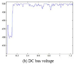 |
Figure 2b |
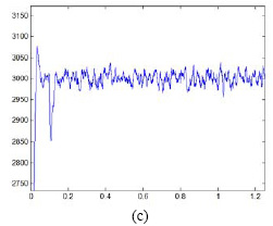 |
Figure 2c |
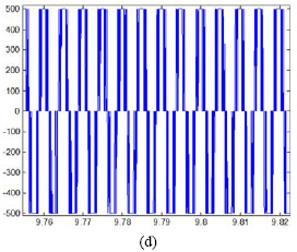 |
Figure 2d |
Analysis of Fuzzy Controller
A heart assist device coupled with the natural heart forms a complicated system. In fact, there are two control strategies. The heart assist system pumps either synchrony to the heart rhythm or asynchrony. In both cases, the systolic pressure and the blood volume flow (cardiac output) are considered as controlling parameters. The controlling parameters are the motor speed and the switching frequency of the solenoid. In the diastolic phase, the motor active length will be reduced due to the axial rotor movement. The speed and the motor current are increased and the losses are decreased. An additional speed control during this time improves the motor efficiency. The synchrony pumping is relatively simple to control, but the heart assistance is not fully effective and the mobility of the patient is restricted (Paraspour & Hanitsch 1994; Guyton 1986, Zadeh 1987, Zadeh L. A., 1978, Zadeh 1987, Pedrycz 1989).
The fuzzy controller has two input variables including blood pressure and cardiac output. The output variables are set speed of the actuator. For purpose of fuzzification of variables in each case, five linguistic terms (very low, low, medium, high and very high) are defined in Figure 3. The membership function of the heart parameters is shown in Figure 4.
 |
Figure 3 |
 |
Figure 4 |
Figure 5 illustrates the block diagram to analyze the dynamics of Block diagram BLDC when using fuzzy block.
Conclusion
The present study has presented and analyzed an electromechanical left ventricular heart assist device driven by a brushless D.C motor and controlled by the fuzzy set theory. For an implantable device, various restrictions should be considered such as fixed low voltage, constant magnetic flux, and upper limit of current density to avoid significant temperature increase and low volume requirements. According to the equations of the electromechanical system and the above mentioned restrictions, an optimization method has been developed in this study.
The optimization method has been used to design and make prototype drive and its electronic control. In combination with the blood circulation, the heart assist device is a nonlinear and multivariable system. In this study, the linguistic description of the system, the optimization of the fuzzy sets and the development of the control rule basis have been realized with regard to the physiological parameters. The fuzzy control algorithm has been proved by an off-line simulation enhanced by the on-line and interactive optimization. The use of the fuzzy logic provides higher robustness and reliability for the medical device, since a fuzzy controller tolerates a certain imprecision in dealing with the controlling problem.
The electromotive and mechanical parameters associated with BLDC motor have provided simulation results according to the literature. Current values are consistent with the data given by the manufacturer in its catalog. At the same time, the real time loads of the model show power values compatible with the application of a ventricular assist device (VAD). The PMSM block was appropriate to present the actuator ICBP and allowed development of a controller. Further studies should be conducted to enhance and improve the dynamic model of control for better power values. Moreover, motor dynamometer tests should be applied for purpose of validating the model dynamic.
References
Andrade, J. Leme A.J, Fonseca J, Bock E, Legendre D, Nicolosy D (2008) Últimos Avanços nos Dispositivos de Assistência Ventricular Brasileiros, 5° COLAOB Congresso Latino Americano de Orgãos Artificiais e Biomateriais.
Bearnson G.B, Jacobs G.B, Kirk J (2006) Heart Quest Ventricular Assist Device Magnetically Levitated Centrifugal Blood Pump,,Journal compilation, International Center for Artificial Organs and Transplantation
Biscegli A.J (2010) Introdução ao Projeto Temático, 1° Encontro Sobre Sistemas Propulsores Eletromagnéticos Implantáveis para Dispositivos de Assistência Circulatória Sanguínea Uni e Biventricular Ou Coração Artificial. São Paulo.
Biscegli A.J, Sousa J.E, Ohashi Y, Nose Y (1997) Flow visualization studies to improve the spiral pump design, Artificial Organs, vol. 21, no. 7, pp. 680-685.
Bock J. E, Ribeiro A, Silva M, Antunes P, Fonseca J, Legendre D (2008) New centrifugal blood pump with dual impeller and double pivot bearing system: Wear evaluation in bearing system performance tests and preliminary hemolysis tests, Artificial Organs, vol. 32, no. 4, pp. 329-333.
Fonseca J.W.G. (2003) Técnica Sensorless para O Acionamento de Motores Brushless DC Aplicados Em Circulação Artificial. Guyton C (1986) Textbook of Medical Physiology, vol. 1.
Hsieh M, Liao H (2010) A Wide Speed Range Sensor less Control Technique of Brushless DC Motors for Eletric Propulsors, Journal of Marine Science and Technology, vol. 18, no. 5, pp. 735-745.
Leão T.F, Fonseca J.W.G, Andrade A.J.P, Bock E.G.P (2009) Desempenho In Vitro do atuador eletromecânico da bomba de sangue centrífuga implantável, Mathworks.
Libre F, Martinez N, Nogarede B (2011) Linear tubular switched reluctance motor for heart assistance circulatory, IEEE
Michael G. M (2004) The Worlds Smallest Magnetic-bearing Turbo Pump, international center for Artificial Organs and Transplantation
Nicolaescu M.A (2012) Rotary Electrical Motors Used Medical Industry, 978-1-4673-1172-4/12/$31.00, IEEE
Paraspour N, Hanitsch R (1994) Fuzzy Controlled Brushless D.C. Motor For Medical Applications,0-7803-1328-3/94$03.00, IEEE
Patel S.M, Penrose H.W, Allaire P.E, Zongli L (2005) An Initial Investigation of Insulation Fault Effects on LVAD Motor Performance, IEEE
Pedrycz W (1989) Fuzzy Control and Fuzzy Systems, John Wiley and sons, Inc.
Shao J (2003) Direct Back EMF Detection Method for Sensorless Brushless DC (BLDC) Motor Drives.
Shao J, Nolan D, Teissier M, Swanson D (2003) A novel microcontroller-based sensorless brushless DC (BLDC) motor drive for automotive fuel pumps, Transactions on Industrial Applications, vol. 39, no. 6, pp. 1734-1740.
Tarcisio F, Bock E, Fonseca J (2012) Modeling Study of an Implantable Centrifugal Blood Pump Actuator with Redundant Sensorless Control, March, pp.11-13.
Viswajith S. Vasudevan, Yu Wang, Marwan A.S (2017) Aortic valve dynamics and blood flow control in continuous flow left ventricular assist devices, IEEE, 10.23919/ACC.2017.7963158, 24-26.
Zadeh L.A (1978) PRUF- a meaning representation language for natural language, Int. J. Man- Machine Studies, vol. 10, pp. 395-460.
Zadeh L.A (1987) Fuzzy Sets and Applications: Selected Papers, 1987, John Wiley and sons, Inc.
Zadeh L.A (1987 a ) Linguistic variables approximate reasoning and dispositions, Int. J. Man-Machine Studies, vol. 10, pp. 395-460.