Department of Computer Science, Sarvestan Branch, Islamic Azad University, Sarvestan, Iran
Corresponding author Email: isi.rahimkhani@gmail.com
Article Publishing History
Received: 12/03/2017
Accepted After Revision: 18/06/2017
Series compensation of transmission lines connected to turbo generators can result in Sub Synchronous Resonance (SSR) leading to adverse torsional oscillations. SSR leads to turbine-generator shaft failure and system instability. The use of Flexible AC Transmission System (FACTS) controllers such as Static Synchronous Compensator (STATCOM) are increasing in the network for enhancing power transfer capability, dynamic voltage support and also damping of power oscillations. STATCOM is one of the most versatile flexible ac transmission system (FACTS) controllers which controls the reactive power flows in transmission lines originating from a substation while controlling the sending end bus voltage. This paper reports the analysis and study of novel supplementary sub synchronous damping controller (SSDC) for STATCOM which is capable of damping out sub synchronous Resonance (SSR) oscillations in power system with series compensated transmission lines. Proposed SSDC for STATCOM is designed based on a hybrid fuzzy optimal controller to damp all SSR torsional oscillations. Simulation results which are obtained by MATLAB, verify the effectiveness of proposed technique and its control strategy for enhancing stability.
Statcom, Oscillation Damping, Fuzzy Controller, Optimal Controller, Sub Synchronous Resonance
Rahimkhani Z. Novel Fuzzy Optimal Controller Based on STATCOM to Damp SSR Oscillations in Series Compensated Systems. Biosc.Biotech.Res.Comm. 2017;10(2).
Rahimkhani Z. Novel Fuzzy Optimal Controller Based on STATCOM to Damp SSR Oscillations in Series Compensated Systems. Biosc.Biotech.Res.Comm. 2017;10(2). Available from: https://bit.ly/2SizyT5
Introduction
Series capacitors have extensively been used as a very effective means of increasing the power transfer capability of transmission lines and improving transient and steady state stability limits of power systems (IEEE SSR Working Group 1985). These improvements are done by compensating reactance of the transmission lines. Besides of having remarkable profits for this kind of compensation for transmission line, the risk of SSR could also be brought to the power system which could cause severe damages to the shaft of the generator unit (Xie et al 2012 and Zhu et al 2014).
SSR is a condition of an electrical power system where electrical networks exchange energy with the mechanical system of the generator at frequencies less than the nominal frequency of the transmission line. At this situation, the turbine-generator oscillates at a frequency corresponding to the torsional mode frequency. The torsional oscillations may raise and result in the failure of the turbine shaft (Orman et al 2012).
Numerous papers have been published about damping the SSR phenomenon, (Fouad et al 1978, Iravani et al 1994), frequency scanning method (Framer et al 1985, Rana et al 2009), time domain simulation (Zhu et al 1995) and using flexible AC transmission systems (FACTSs) controllers such as the static synchronous series compensator (SSSC) Padiyar et al (2006) (Bongiorno et al (2008), the unified power flow controller (UPFC) (Bo et al (2002), the thyristor controlled series capacitor (TCSC) (Pilotto et al (2003)) and high voltage direct current (HVDC) transmission systems (Jiang et al (2005) have been applied to prevent the SSR in power systems.
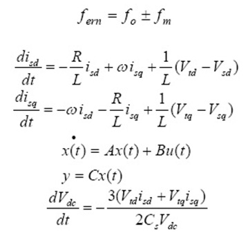
Rotor oscillations of generator at a torsion mode frequency, (fm) induce armature voltage components at frequencies (fern) given by: When the sub synchronous component term is close to electrical resonant frequency, the sub synchronous torques produced by sub synchronous voltage components can be sustained. This interplay between electrical and mechanical systems is termed as torsional oscillations ( Xie et al (2012).
As a new type of reactive power compensation FACTS device, STATCOM has a fast and smooth control performance. By applying appropriate control strategies, STATCOM could be used to damp power frequency oscillation, enhancing power transfer and voltage stability.
In this paper, the damping of torsional oscillations using STATCOM has been studied and novel supplementary sub synchronous damping controller based on fuzzy optimal technique is proposed. Optimal control method which is used along fuzzy damping controller will be designed based on linear quadratic regulator (LQR) that minimizes the cost function in order to achieve the optimal tradeoff between the use of control effort, the magnitude and the speed of response. Also it guarantees a stable control system. The Fuzzy logic is used to design of control system in outer loops of controller and designed supplementary controller for damping oscillation in STATCOM. Simulation results which is obtained by MATLAB, verifies the effectiveness of the STATCOM and its control strategy for damping SSR oscillations.
Dynamic Modelling Of Statcom
The system considered is an IEEE benchmark used to study subsynchronous resonance. The modeling aspects of the electromechanical system are given in detail in reference. This system is shown in Fig.1.
One convenient method for studying balanced three-phase system (especially in synchronous machine problems) is to convert the three phase voltages and currents into synchronous rotating frame by abc/dq transformation. The benefits of such arrangement are: the control problem is greatly simplified because the system variables become DC values under balanced condition; multiple control variables are decoupled so that the use of classic control method is possible, and even more physical meaning for each control variable can be acquired. Equations (2) to (4) give the mathematical expression of the STATCOM shown in Fig 1.
 |
Figure 1: Single line diagram of IEEE benchmark test system |
Fig. 2 illustrates the detailed control block diagram of STATCOM according to dynamic equations (Xin et al 2009 and Yidan et al 2011).
 |
Figure 2: The detailed control block diagram of STATCOM |
Optimal Controller Based On Lqr
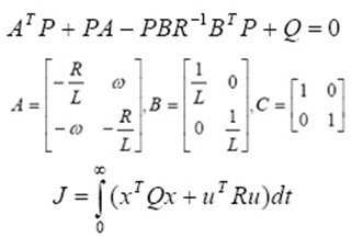
The theory of optimal control is concerned with operating a dynamic system at minimum cost. The case where the system dynamics are described by a set of linear differential equations and the cost is described by a quadratic function is called the LQ problem. One of the main results in the theory is that the solution is provided by the linear-quadratic regulator (LQR), a feedback controller whose equations are given below.
This method determines the feedback gain matrix that minimizes the cost function in order to achieve the optimal tradeoff between the use of control effort, the magnitude and the speed of response. In addition, this method guarantees a stable control system.
Given a linear system:
Where x (t) are the system’s states, u(t) is the system input and y(t) is the output. The objective is to design a feedback u(t) = –Kx(t) such that the cost function (4) can be minimized:
The weighting matrices Q and R are positive semi-definite. They control how much effort should be put on the controller. The feedback gain K is obtained by getting matrix P first via solving the Riccati equation:
Therefore,
When the feedback gain K is obtained, the LQR controller can be easily designed to make the states approach zeros optimally.
Writing equations (2), (3) and (4) in the state space format as (5), the corresponding matrix can be found as:
Where, the states , the inputs
 and the output are
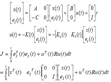
Since the LQR controller is designed to drive the states to zero. This is very restrictive and not suitable for solving tracking system problem. In the STATCOM control, line currents are to be followed. Therefore, alteration must be applied to the LQR controller in order to drive the current errors, instead of the currents, to zero. To achieve zero steady state errors, an integrator is inserted in the control loop and the original system is augmented to include the errors as new system states (Xie et al (2012).
In equation (8),
Rewrite the cost function in format of (10), it shows that the new LQR regulator is aimed in minimize the errors.
The control block diagram of the LQR current control loop which is proposed for STATCOM is shown in Fig.3.
 |
Figure 3: The control block diagram of the LQR current control loop |
Controller Design Based On Fuzzy Logic
Fuzzy control is a control method based on fuzzy logic. Just as fuzzy logic can be described simply as “computing with words rather than numbers”; fuzzy control can be described simply as “control with sentences rather than equations” (Jang et al 2010). A fuzzy controller can include empirical rules, and that is especially useful in operator controlled plants.Different parts of fuzzy controller are shown in Fig.4.
 |
Figure 4: Common Structure of Fuzzy Controller |
The major components of a typical fuzzy controller are fuzzification, fuzzy rule base, fuzzy inference, and defuzzification. Fuzzification is the process of decomposing a system input and/or output into one or more fuzzy sets. A fuzzy set is represented by a membership function defined on the universe of discourse. Fuzzy rules represent the control strategy. They are linguistic if-then statements involving fuzzy set, fuzzy logic, and fuzzy inference (Single et al 2013).
Fuzzy rules play a key role in representing expert control knowledge and experience and in linking the input variables of fuzzy controllers to output variable (or variables). Fuzzy inference is used in a fuzzy rule to determine the rule outcome from the given rule input information (Mon et al (2013).
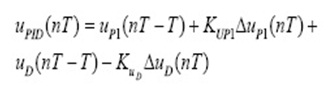
In this article a fuzzy PI-D control units is used with the STATCOM control circuit. This controller is shown in Fig.5.in this figure the derivation of the fuzzy control law is performed in two steps: one for the output of the fuzzy PI controller and the other for the output of the fuzzy D controller. The final control law combines these two individual control laws together in an appropriate way. As follow:
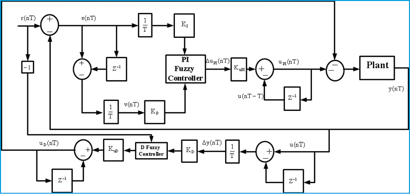 |
Figure 5: PI-D Fuzzy Controller |
Proposed Optimal Pi-D Fuzzy Controller For Ssr Oscillations Damping
In this article optimal control method based on LQR minimizes the cost function in order to achieve the optimal tradeoff between the use of control effort, the magnitude and the speed of response. Also it guarantees a stable control system. The Fuzzy logic based on PI-D controller is implemented to control system in outer loops of controller and designed supplementary controller for damping oscillation in STATCOM.
It is well known that damping of power system oscillations can be improved by developing a torque in phase with the speed deviation. Choice of a measurable input signal is the main consideration in the design of a damping controller. So for damping purposes, speed deviation of the generator is used as input to the damping controller and added to the outer dc voltage control loop. This signal brings to a controller who designed based PI-D fuzzy controller based on optimal controller as it shown in Fig.6.
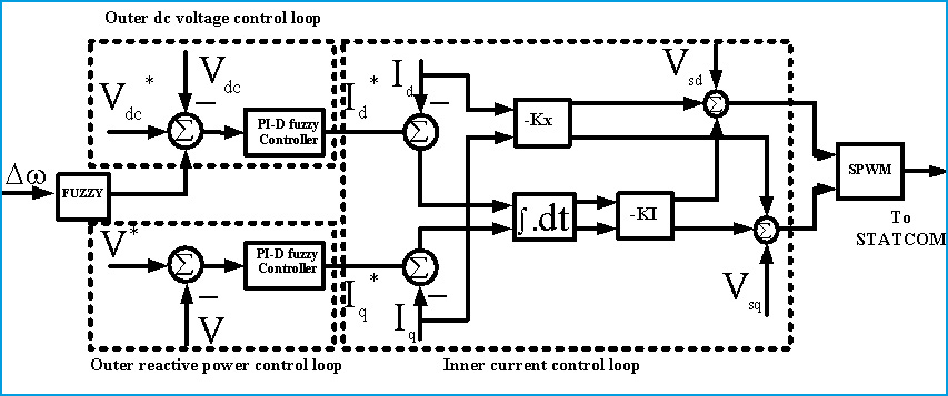 |
Figure 6: Proposed Optimal Fuzzy PI-D Supplementary Damping Controller |
Simulation Results
In this paper the case study system is an IEEE benchmark used to study sub synchronous resonance and particularly torque amplification. It consists in a single generator (600 MVA/22kV/60 Hz/3600 rpm) connected to an infinite bus via two transmission lines, one of which is 55% series-compensated.
The sub synchronous mode introduced by the compensation capacitor after a three-phase fault has been applied and cleared excites the oscillatory torsional modes of the multi-mass shaft and the torque amplification phenomenon can be observed. The mechanical system is modeled by 3-masses: mass 1 = generator; mass 2 = low pressure turbine (LP); mass 3 = high pressure turbine (HP).
Disturbances are accrued in system according table.1.
| Table 1: Disturbances | |
| Type of Disturbance | Time of Occurrence |
| 3 phase fault | |
| Add a Inductive Load | |
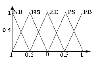
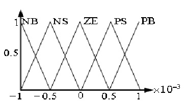
Fig.7 shows the membership functions for fuzzy controller that used in outer dc voltage control loop. Error, deviation error and controller output range for all fuzzy controllers are shown in Table.2.
| Table 2: Fuzzy controller’s rules | |||||
| |
PB | PS | ZE | NS | NB |
| PB | PB | PB | PS | PS | ZE |
| PS | PB | PS | PS | ZE | NS |
| ZE | PS | PS | ZE | NS | NS |
| NS | PS | ZE | NS | NS | NB |
| NB | ZE | NS | NS | NB | NB |
| Table 3: Fuzzy controller’s information | |||
| Fuzzy controllers | Range | ||
| Error | Error Deviation | Output | |
| Outer dc voltage control loop | [-1,1] | [-0.001,0.001] | [-20,20] |
| Outer reactive power control loop | [-1,1] | [-1,1] | [-10,10] |
| Supplementary damping controller | [-0.1,-0.1] | [-0.001,0.001] | [-1,1] |
|
Figure 7: Membership functions for outer dc voltage control loop (a) Error(b)Deviation Error |
Fuzzy rules that are in fuzzy controllers are shown in Table.2.
Figures 8-12 describe the response of series compensated system without STATCOM. Figures 8-10 are shown rotor speed of generator and High and Low pressure turbine shaft speed. Fig. 11 presents torque between generator and low pressure and Fig. 12 show torque between generator and high pressure. It is obvious that the compensated system with series capacitive will be unstable when a 3 phase fault is occurred.
 |
Figure 8: Generator Speed Deviation |
 |
Figure 9: Low pressure turbine speed deviation |
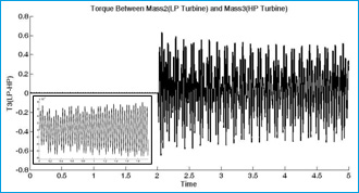 |
Figure 10: High pressure turbine speed deviation |
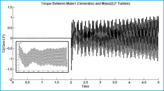 |
Figure 11: Torque between generator and low pressure turbine |
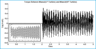 |
Figure 12: Torque between low pressure and high pressure turbine |
Figures 13-24 are shown system characterizations after STATCOM installation. Fig. 13 presents the output voltage of STATCOM which is changed on during the faults. Fig.14. shows the rotor speed deviation of different masses in shaft-rotor system. As it is shown, oscillations in speed are damping during the simulation time especially when faults are accrued.
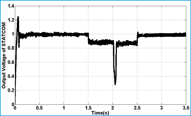 |
Figure 13: Output Voltage of STATCOM |
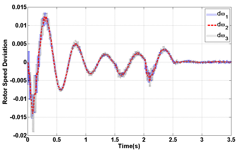 |
Figure 14: Rotor Speed Deviation |
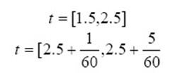
Fig.15. represents torque deviation on different masses. Because of using damping controller in STATCOM, torque oscillations are damping. Based on control strategy in STATCOM, DC voltage of converter must be constant in all time of simulation. Fig.15. demonstrate this fact. Figs.16.17. show the three level output voltage of converter. Also, voltages of buses are shown in Fig.17-Fig.21. all voltage has negligible harmonic because of appropriate filter tuning in output of inverter. Current components are shown in Fig.22-24. Position of this current was shown in Fig.6. This is describing proposed technique in this article.
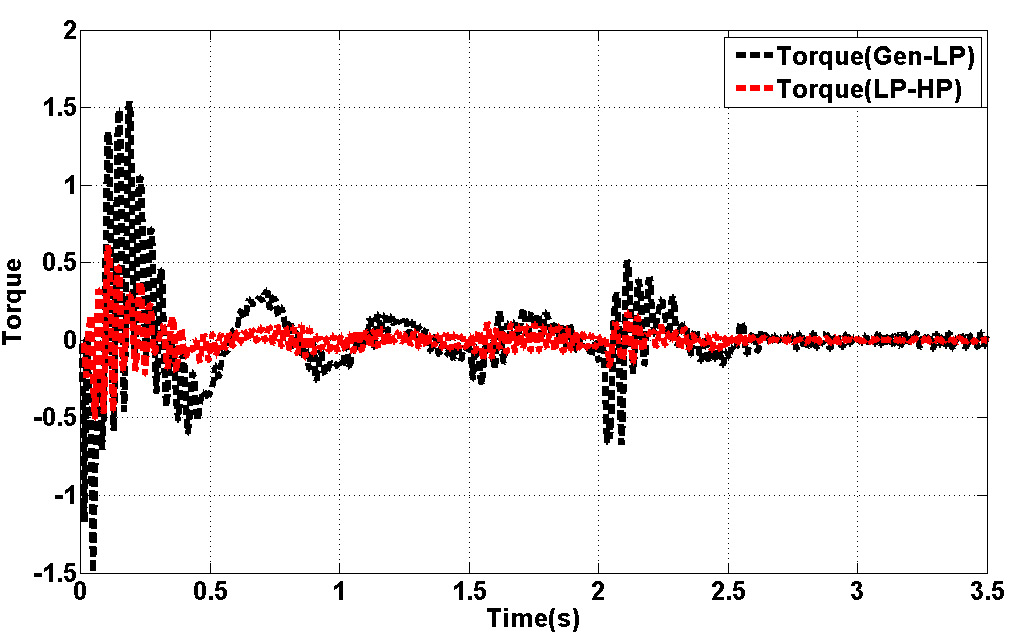 |
Figure 15: Torque Deviation in Rotor of SM |
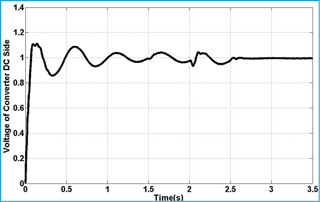 |
Figure 16: Voltage of DC Capacitor in STATCOM |
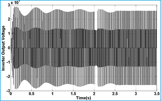 |
Figure 17: Inverter Output Voltage |
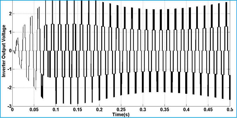 |
Figure 18: Inverter Output Voltage (0-0.5s) |
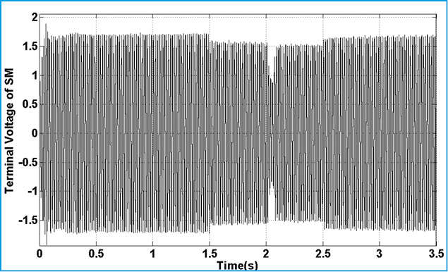 |
Figure 19: Terminal Voltage of SM |
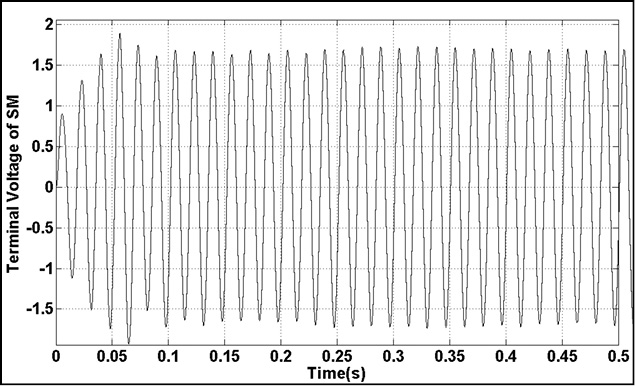 |
Figure 20: Terminal Voltage of SG(0-0.5) |
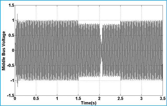 |
Figure 21: Middle Bus Voltage |
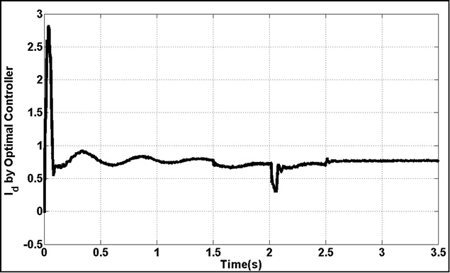 |
Figure 22: Active Component of LQR Controller |
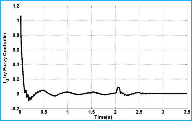 |
Figure 23: Active Component of Fuzzy Controller |
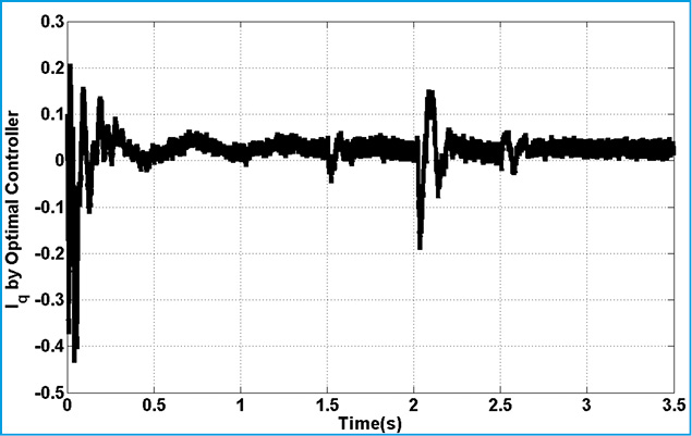 |
Figure 24: Reactive Component of LQR Controller |
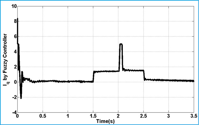 |
Figure 25: Reactive Component of LQR Controller |
Conclusion
In this paper, a novel supplementary subsynchronous damping controller (SSDC) for STATCOM which is capable of damping out subsynchronous Resonance (SSR) oscillations in power system is proposed. This damping controller is designed based on optimal PI-D fuzzy controller. The presented simulation results show that STATCOM based on proposed controller is capable to power system oscillation damping and. The simulation results support the applications of optimal fuzzy controller in power systems.
References
- Zhu,X., H.Sun, J.Wen, S.Chen (2014), A practical method to construct network state equations in multi-machine system SSR study”, Electric Power Systems Research 107, pp 51– 58.
- Bo, W Z. Yan (2002), Damping subsynchronous oscillation usingUPFC—aFACTS device, in Proc. Int. Conf. Power System Technology, vol. 4—PowerCon 2002, October 13–17, pp. 2298–2301.
- Bongiorno, M., L.Ängquist, J.S.Lennart (2008), “A novel control strategy for subsynchronous resonance mitigation using SSSC”, IEEE Trans. Power Electron, pp 1033–10041.
- Bongiorno, M., J. Svensson, L. Ängquist (2008), “On control of static synchronous series compensator for SSR mitigation”, IEEE Trans. Power Electron, pp 735–743.
- Edris A(1990), Series compensation schemes reducing the potential of resonance, IEEE Trans PAS, pp219–26.
- Fouad AA (1978), Khu KT. Subsynchronous resonance zones in the IEEE bench mark power system IEEE Trans PAS, PAS-97(15), pp 754–62.
- Framer RG, Katz E, Schwalb AL. Navajo (1985), Project on sub synchronous resonance analysis and solutions IEEE Trans PAS, pp1057–66.
- IEEE SSR Task Force, First benchmark model for computer simulation of sub synchronous resonance, IEEE Trans. Power Appl. Syst. PAS-96 (September/October) 1562–1572.
- IEEE SSR Working Group (1985), Terms, definitions and symbols for sub synchronous oscillations, IEEE Trans. Power Appl. Syst. PAS-104 (June (6)), pp1326–1334.
- IEEE Sub synchronous Resonance working group, Second benchmark model for computer simulation of sub synchronous resonance, IEEE Transactions on Power Apparatus and Systems, vol. PAS-104, no. 5, 1985, pp. 1057-1066.
- Iravani MR, Edris AA (1994), “Eigen analysis of series compensation schemes reducing the potential of sub synchronous resonance”. IEEE Power System Summer Meeting.
- Jang JSR, C.T. Sun & E (2010). Mizutani: Neuro Fuzzy and Soft Computing”, PHI Learning.
- Li Yidan, Lu Wensheng, Peng Xiuyan (2011), DC voltage measurement and control for cascaded STATCOM”, Proceedings of the CSEE, Vol. 1, Issue 31, pp. 14-19.
- Liu X Single (2013), Neuron Self-tuning PID Control for Welding Molten Pool Depth, Proceedings of the 7 Th World Congress on Intelligent Control and AutomationJune 25-27, Chongqing, China
- Mon, YJ C.M. Lin & I.J. Rudas (2013), ANFIS-based Wireless Sensor Network (WSN) Applications for Air Conditioner Control, Acta Polytechnica Hungarica, Vol. 10, No. 3, pp. 5-16
- Orman,M., P.Balcerek, M.Orkisz (2012), Effective method of subsynchronous resonance detection and its limitations”, Electrical Power and Energy Systems 43, pp915–920
- Padiyar, K., N.Prabhu (2006), Design and performance evaluation of sub synchronous damping controller with STATCOM”, IEEE Trans. Power Deliv. 21 (July (3)), pp1398–1405.
- Pahlavani, M., H.Mohamadpour (2011), Damping of sub-synchronous resonance and low-frequency power oscillation in a series-compensated transmission line using gate-controlled series capacitor”, Electric Power Systems Research 81, pp 308–317.
- Pilotto, LAS A. Bianco, W.F. Long (2003), A.A. Edris, Impact of TCSC control methodologies on subsynchronous oscillations, IEEE Trans. Power Deliv, pp 243–252.
- Quanyuan Y. Jiang, Yijia J. Cao and Shijie J. Cheng (2005), A Genetic Approach to Design a HVDC Supplementary Subsynchronous Damping Controller”, IEEE Transactions On Power Delivery, Vol. 20, NO.2.
- Rana RD, Huff SW, Hayes RM, Fromholtz EN, Schulz RP (2009), AEP’s Kanawha river 345kV series capacitor installations-subsynchronous resonance studies and torsional measurements”, In Proceedings of the American power conference, p 300–5.
- Wei Wenhui, Liu Wenhua, Song Qiang (2005), Research on fast dynamic control of static synchronous compensator using cascade multilevel inverters”, Proceedings of the CSEE, Vol. 25, Issue 2, pp. 23-26.
- Xie, XR Y.P. Dong, Y.D. Han (2012), “Online estimation of turbine–generator shaft fatigue loss-of-life caused by sub synchronous resonance”, Electric Power Systems Research 92, pp 171–179.
- Xin, L.Shao Wenchang, Yang Shuying (2009), Multi- loop control scheme of grid side converter with LCLfilter, Journal of Hefei University of Technology, Vol. 7, Issue 32, pp 972-976.
- Yan A, Yu Y (1982), Multi-mode stabilization of torsional oscillations using output feedback excitation control, IEEE Trans PAS, PAS-101, pp 1245–53.
- Zhu W, Spee R, Mohler RR, Alexander GG, Mittelstadt WA, Maratuhulam D (1995), “An EMTP study of SSR mitigation using the thyristor controlled series capacitor”, IEEE Trans Power, pp 10:1479–85.