1Management Information System and Computer Science Department, Future Academy, Cairo-Egypt
2Information Technology Deanship King Abdulaziz University Jeddah, Kingdom of Saudi Arabia
Corresponding author Email: Mona.abdelkareem@fa-hists.edu.eg
Article Publishing History
Received: 02/01/2019
Accepted After Revision: 28/03/2019
The objective of the current thesis is to find the best filter of the digital image in a fast way. Image restoration concerns the removal or reduction of degradations which have occurred during the acquisition of the image. Such degradations may include noise, which are errors in the pixel values position, or optical effects such as out of focus blurring, or blurring due to camera motion. We shall see that some restoration techniques can be performed very successfully using neighborhood operations, while others require the use of frequency domain processes. Image restoration remains one of the most important areas of image processing. All kinds of filters have been tested to select the one that gives the best filtered image quality. It looks from the image results that the average filter is better for removing the noise then median filter and the last wiener filter.
Transform, Salt And Pepper Noise, Gaussian Noise, Mean Filter, Median Filter
El-Kareem M. A, El-Emary I. M. M. Towards Developing An Advanced Methodology For Image Enhancement Based On Z-Transform. Biosc.Biotech.Res.Comm. VOL 12 NO1 (Spl Issue February) 2019.
El-Kareem M. A, El-Emary I. M. M. Towards Developing An Advanced Methodology For Image Enhancement Based On Z-Transform. Biosc.Biotech.Res.Comm. VOL 12 NO1 (Spl Issue February) 2019. Available from: https://bit.ly/2xsb6Fl
Introduction
All kinds of filters have been tested to select the one that gives the best filtered image quality. The z-transform is useful for the manipulation of discrete data sequences and has acquired a new significance in the formulation and analysis of discrete-time systems. It is used extensively today in the areas of applied mathematics, digital signal processing, control theory, population science, and economics. These discrete models are solved with difference equations in a manner that is analogous to solving continuous models with differential equations [7]. System analysis in frequency domain can also be more convenient as differentiation and integration operations are performed through multiplication and division by the frequency variable respectively. Furthermore the transient and the steady state characteristics of a system can be predicted by analyzing the roots of the Laplace transform or the z-transform, the so-called poles and zeros of a system. A special feature of the z-transform is that for the signals and system of interest to us , all of the analysis will be in terms of ratios of polynomial. Working with these polynomials is relatively straight forward. Digital filtering is a widely used technique that is common in many fields of science and engineering.[10] Filters remove unwanted signals and noise from a desired signal. There are many different kinds of filters, including mean, median and wiener filters.
Aspects of Image Processing
Modern digital technology has made it possible to manipulate multi-dimensional signals with systems that range from simple digital circuits to advanced parallel computers. The goal of this manipulation can be divided into three categories:
- Image Processing (image in -> image out)
- Image Analysis (image in -> measurements out)
- Image Understanding (image in -> high-level description out)
An image may be considered to contain sub-images sometimes referred to as regions-of-interest, ROIs, or simply regions. This concept reflects the fact that images frequently contain collections of objects each of which can be the basis for a region. In a sophisticated image processing system it should be possible to apply specific image processing operations to selected regions. Thus one part of an image (region) might be processed to suppress motion blur while another part might be processed to improve color rendition. Sequence of image processing:
Most usually, image processing systems require that the images be available in digitized form, that is, arrays of finite length binary words. For digitization, the given Image is sampled on a discrete grid and each sample or pixel is quantized using a finite number of bits. The digitized image is processed by a computer. To display a digital image, it is first converted into analog signal, which is scanned onto a display.
Before going to processing an image, it is converted into a digital form. Digitization includes sampling of image and quantization of sampled values. After converting the image into bit information, processing is performed. This processing technique may be Image enhancement, Image restoration, and Image compression.38
Image Enhancement
It refers to accentuation, or sharpening, of image features such as boundaries, or contrast to make a graphic display more useful for display & analysis. This process does not increase the inherent information content in data. It includes gray level & contrast manipulation, noise reduction, edge crispening and sharpening, filtering, interpolation and magnification, pseudo coloring, and so on.
Image Restoration
It is concerned with filtering the observed image to minimize the effect of degradations. Effectiveness of image restoration depends on the extent and accuracy of the knowledge of degradation process as well as on filter design. Image restoration differs from image enhancement in that the latter is concerned with more extraction or accentuation of image features.
Image Compression
It is concerned with minimizing the number of bits required to represent an image. Application of compression are in broadcast TV, remote sensing via satellite, military communication via aircraft, radar, teleconferencing, facsimile transmission, for educational & business documents, medical images that arise in computer tomography, magnetic resonance imaging and digital radiology, motion, pictures, satellite images, weather maps, geological surveys and so on.
Model of Image Degradation
In the spatial domain, we might have an image f(x,y) and a spatial filter h(x,y) for which convolution with the image results in some form of degradation. For example, if h(x,y) consists of a single line of ones, the result of the convolution will be a motion blur in the direction of the line [8].
Thus we may write g(x,y) = f(x,y) * h(x,y) for the degraded image, where the symbol * represents spatial filtering. However, this is not all. We must consider noise, which can be modeled as an additive function to the convolution. Thus if n(x,y) represents random errors which may occur, we have as our degraded image:
![]()
We can perform the same operations in the frequency domain, where convolution is replaced by multiplication, and addition remains as addition, because of the linearity of the Fourier transform.
Thus G(i,j) = F(i,j) H(i,j) + N(i,j) represents general image degradation, where of course F, H and N are the Fourier transforms of f, h and n respectively.
If we knew the values of H and N we could recover F by writing the above equation as
![]()
However, as we shall see, this approach may not be practical. Even though we may have some statistical information about the noise, we will not know the value of n(x,y) or N(i,j) for all, or even any, values. As well, dividing by H(i,j) will cause difficulties if there are values which are close to, or equal to, zero,(see the figure below).
Z-Transform
The structure and features of the given signal may be better understood by transforming the data into another domain. In general the Z-transform of any function written explicitly can be found for a set of frequencies in a certain domain at our choice. Applying any of the filters, we use the Z-transform for specified intervals. Then we take the inverse Z-transform to get the required filtered image. The results are promising and make you think of using different filters or different transform.We set the z-transform at some specified frequencies, which are connected the grid distance used in the image display. [2] System analysis in frequency domain can also be more convenient as differentiation and integration operations are performed through multiplication and division by the frequency variable respectively. [11] Furthermore the transient and the steady state characteristics of a system can be predicted by analyzing the roots of the Laplace transform or the z-transform, the so-called poles and zeros of a system. A special feature of the z-transform is that for the signals and system of interest to us. all of the analysis will be in terms of ratios of polynomial. Working with these polynomials is relatively straight forward. [9]
Noise in Digital Images
Digital images are prone to a variety of types of noise. Noise is the result of errors in the image acquisition process that result in pixel values that do not reflect the true intensities of the real scene. There are several ways that noise can be introduced into an image, depending on how the image is created. For example:
- If the image is scanned from a photograph made on film, the film grain is a source of noise. Noise can also be the result of damage to the film, or be introduced by the scanner itself.
- If the image is acquired directly in a digital format, the mechanism for gathering the data (such as a CCD detector) can introduce noise.
Amplifier Noise (Gaussian Noise)
The standard model of amplifier noise is additive, Gaussian, independent at each pixel and independent of the signal intensity. In color cameras where more amplification is used in the blue color channel than in the green or red channel, there can be more noise in the blue channel .Amplifier noise is a major part of the “read noise” of an image sensor, that is, of the constant noise level in dark areas of the image[3] [4].
Salt-and-Pepper Noise
An image containing salt-and-pepper noise will have dark pixels in bright regions and bright pixels in dark regions [4]. This type of noise can be caused by dead pixels, analog-to-digital converter errors, bit errors in transmission, etc. This can be eliminated in large part by using dark frame subtraction and by interpolating around dark/bright pixels.
Speckle Noise
Speckle noise is a granular noise that inherently exists in and degrades the quality of the active radar and synthetic aperture radar (SAR) images. Speckle noise in conventional radar results from random fluctuations in the return signal from an object that is no bigger than a single image-processing element. It increases the mean grey level of a local area. Speckle noise in SAR is generally more serious, causing difficulties for image interpretation. It is caused by coherent processing of backscattered signals from multiple distributed targets. In SAR oceanography [5], for example, speckle noise is caused by signals from elementary scatters, the gravity-capillary ripples, and manifests as a pedestal image, beneath the image of the sea waves.
Different Types of Filters
In this section we review the different types of filter.
Mean Filter
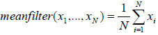
Can use linear filtering to remove certain types of noise. Certain filters, such as averaging or Gaussian filters, are appropriate for this purpose. For example, an averaging filter is useful for removing grain noise from a photograph. Because each pixel gets set to the average of the pixels in its neighborhood, local variations caused by grain are reduced. Conventionally linear filtering Algorithms were applied for image processing. The fundamental and the simplest of these algorithms is the Mean Filter as defined in [6].The Mean Filter is a linear filter which uses a mask over each pixel in the signal. Each of the components of the pixels which fall under the mask are averaged together to form a single pixel. This filter is also called as average filter. The Mean Filter is poor in edge preserving. The Mean filter is defined by:
where (x1,…,xN) is the image pixel range. Generally linear filters are used for noise suppression.
Median Filter
The Median filter is a nonlinear digital filtering technique, often used to remove noise. Such noise reduction is a typical preprocessing step to improve the results of later processing (for example, edge detection on an image). Median filtering is very widely used in digital image processing because under certain conditions, it preserves edges whilst removing noise. The main idea of the median filter is to run through the signal entry by entry, replacing each entry with the median of neighboring entries. Note that if the window has an odd number of entries, then the median is simple to define: it is just the middle value after all the entries in the window are sorted numerically. For an even number of entries, there is more than one possible median. The median filter is a robust filter. Median filters are widely used as smoothers for image processing, as well as in signal processing and time series processing. A major advantage of the median filter over linear filters is that the median filter can eliminate the effect of input noise values with extremely large magnitudes. (In contrast, linear filters are sensitive to this type of noise – that is, the output may be degraded severely by even by a small fraction of anomalous noise values) [6]. the output y of the median filter at the moment t is calculated as the median of the input values corresponding to the moments adjacent to t:
![]()
wheret is the size of the window of the median filter. Besides the one-dimensional median filter described above, there are two-dimensional filters used in image processing .Normally images are represented in discrete form as two dimensional arrays of image elements, or “pixels” – i.e. sets of non-negative values Bij ordered by two indexes –
i =1,…,Ny (rows) and j = 1,…,Ny (column).
where the elements Bij are scalar values, there are methods for processing color images, where each pixel is represented by several values, e.g. by its “red”, “green”, “blue” values determining the color of the pixel.
Wiener Filter
The goal of the Wiener filter is to filter out noise that has corrupted a signal. It is based on a statistical approach. Typical filters are designed for a desired frequency response. The Wiener filter approaches filtering from a different angle. One is assumed to have knowledge of the spectral properties of the original signal and the noise, and one seeks the LTI filter whose output would come as close to the original signal as possible [1].
Wiener filters are characterized by the following:
- Assumption: signal and (additive) noise are stationary linear random processes with known spectral characteristics.
- Requirement: the filter must be physically realizable, i.e. causal (this requirement can be dropped, resulting in a non-causal solution)
- Performance criteria: minimum mean-square error
The Proposed Methodology of Image Enhancement
On our technique we do, first we choose brain computed tomography image then we add Noise to the Digital Images then Using Some Elementary Filters with standard deviation (0.025) To select the one that gives the best filtered image quality
Digital images are prone to a variety of types of noise. Noise is the result of errors in the image acquisition process that result in pixel values that do not reflect the true intensities of the real scene. There are several ways that noise can be introduced into an image, depending on how the image is created noise in an image can be cancelled indirectly by using the frequency domain , which can be first obtained by using the Z-transform of the original image at certain frequency then utilizing one of the filters to smooth out the frequency domain.
Simulated Output Results
The Original Image is brain ct image, adding three types of Noise (Gaussian noise, Speckle noise and Salt & Pepper noise). Adding the noise with standard deviation(0.025) and De-noised image using Mean filter, Median filter and Wiener filter and comparisons among them 9. We used the brain ct Image (fig. 1) in “jpeg” format ,adding two noise (Gaussian and Salt & Pepper) in original image with standard deviation (0.025) (fig. to fig. 4) ,removing noise from all noisy images by all filters and conclude from the results (fig. 5 to fig.13) .
 |
Figure 1: Original image |
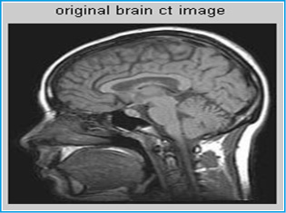 |
Figure 1 a |
 |
Figure 2. Adding salt & pepper noise with standard deviation (0.025) |
 |
Figure 3: Adding Gaussian noise with standard deviation (0.025) |
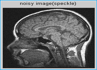 |
Figure 4: Adding speckle noise with standard deviation (0.025) |
 |
Figure 5: Removing noise by median filter |
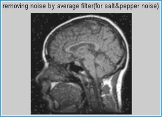 |
Figure 6: Removing noise by mean filter |
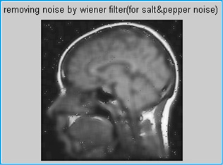 |
Figure 7: Removing noise by wiener filter |
 |
Figure 8: Removing noise by median filter |
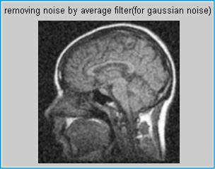 |
Figure 9: Removing noise by mean filter |
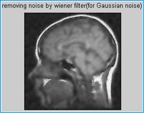 |
Figure 10: Removing noise by wiener filter |
 |
Figure 11: Removing noise by median filter |
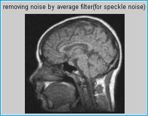 |
Figure 12: Removing noise by mean filter |
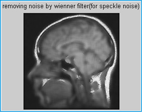 |
Figure 13: Removing noise by wiener filter |
All kinds of filters have been tested to select the one that gives the best filtered image quality. It looks from the image results that the average filter is better for removing the noise then median filter and the last wiener filter. In the future work, this software work could be made to be hardware work which could be used on routine bases. Image could also be related to time where we can see the image in movie form.
References
- Wavelet domain image de-noising by thresholding and Wiener filtering. Kazubek, M. Signal Processing Letters, IEEE, Volume: 10, Issue: 11, Nov. 2003 265 Vol.3.
- Mark A. WickertIntroduction to signal and system, ECE 2610 Lecture Notes Spring 2011
- J. Portilla, V. Strela, M. J. Wainnwright, and E. P. SimocelliAdaptive Wiener denoising using a Gaussian scale mixture model in the wavelet domain Proc. 8th Int. Conf. Image Processing, 2001.
- Charles Boncelet (2005) Image Noise Models in Alan C. Bovik. Handbook of Image and Video Processing.
- Sedef Kent, Osman NuriOçan, and TolgaEnsari (2004).Speckle Reduction of Synthetic Aperture Radar Images Using Wavelet Filtering in astrium. EUSAR 2004 Proceedings, 5th European Conference on Synthetic Aperture Radar, May 25–27, 2004, Ulm, Germany.
- James C. Church, Yixin Chen, and Stephen V. Rice Department of Computer and Information Science, University of Mississippi, A Spatial Median Filter forNoise Removal in Digital Images IEEE, page(s): 618-623, 2008.
- Alberto Bemporad, Automatic Control 1Z-transform University of Trento, Academic year 2010-2011.
- Mark A. WickertIntroduction to signal and system ECE 2610 Lecture Notes Spring 2011
- Fazarinc, ZvonkoZ-transform and its application to development of scientific simulation algorithms, Computer Applications in Engineering Education Volume 21, Issue 1, pp. 75-88, Mar 2013
- Alasdair McAndrew An Introduction to Digital Image Processing with MatlabNotes for SCM2511 Image Processing 1 Semester 1, 2004.
- Alberto Bemporad, Automatic Control 1Z-transform, University of Trento, Academic year 2010-2011