1Department of Electrical Engineering, College of Engineering, University of Basra, Iraq
2Department of Computer Engineering, College of IT, University of Bahrain, Bahrain
3Department of Systems Engineering, College of Engineering and Information Technology, University of Arkansas at Little Rock, USA
Corresponding author Email: aalomary@uob.edu.bh
Article Publishing History
Received: 12/11/2018
Accepted After Revision: 19/12/2018
Cooperative relay has been recently employed to resolve the problem arises from fading and multipath propagation. Bit Error Rate (BER) is one of key metrics used for system performance assessment. This paper provides analytical formulation for the BER as a function of distance employing 4Quadrature Amplitude Modulation (4QAM). Impact location of the relays and effects of different propagation environment is considered. Also, impact of AF relay in reducing the required SNR in case using 4QAM is presented. Results show that the best location of relays is in the center between the source and destination. Also, using relays reduce the SNR, which reduces the power of the transmitted signal.
Amplify And Forward (Af) Relaying; 4qam; Rayleigh Channel; Ber; Cooperative Relaying
AL-Khafaji H. A, Al Sabbagh H. M, Al-Omary A, Al-Rizzo H. Performance Analysis of 4QAM for AF Relays over Rayleigh Fading Channel. Biosc.Biotech.Res.Comm. VOL 12 NO1 (Spl Issue February) 2019.
AL-Khafaji H. A, Al Sabbagh H. M, Al-Omary A, Al-Rizzo H. Performance Analysis of 4QAM for AF Relays over Rayleigh Fading Channel. Biosc.Biotech.Res.Comm. VOL 12 NO1 (Spl Issue February) 2019. Available from: https://bit.ly/2LwGqeg
Introduction
Many enhanced technologies of wireless networks have been investigated and contributed by academia and industry over the past few decades, relay is one of the most attractive technologies [1]. Transmitting independent copies of signal generates diversity may be generated by transmitting signals from different locations, thus allowing independently faded versions of the signal at the receiver. Cooperative communication enables this type of cooperative diversity [2]. In [3] authors derive closed-form expressions of the exact bit error rate computation for cooperative communication systems for 4/16 QAM modulation over additive white Gaussian noise (AWGN) channels and Rayleigh fading channels.Suraweera et al., [4] derived closed-form expressions for the outage probability in Nakagami/Generalized-K and Generalized-K/Nakagami fading environments. Based on the obtained formulas, new expressions for the average bit error probability of rectangular QAM modulations were also derived. Trigui et al. [5] have investigated the outage probability of a single relay transmitting over different channel condition. Also, investigated the perfeormance of the system in term of BER for 4 and 16 QAM.
This paper provides analytical formulation for the BER in terms of distances between source, relay and destination with existence of direct path. The BER simulated for a different relay locations with a specific propagation environment. Also, compare the performance of the system with and without employing relays and show how the relay enhance reduing the SNR with using 4QAM modulation. Finally, investigating effect of different propagation environments on the BER of multiple AF relay.
The rest of the paper is organized as follows. In Section 2, the system model of the considered AF system is described. In Section 3, results and discussion are presented. Finally, Section 4 concludes the paper.
| Table 1: The BER for three relays when dsr2 = 0.5 at different SNR | |||
| á | SNR=2dB | SNR=4dB | SNR=6dB |
| 3 | 9×10⁻³ | 2×10⁻³ | 4×10⁻⁴ |
| 4 | 2×10⁻³ | 3×10⁻⁴ | 7×10⁻⁵ |
| 5 | 6×10⁻⁴ | 6×10⁻⁵ | 1×10⁻⁵ |
System Model
Large-scale fading in wireless system occurs when the transmitted signal passes through large distances compared to the wavelength and obstacles causing shadowing and path loss. Influence of the propagation environment in addition to the loss of signal power as a function to the propagation distance cause path loss, while shadowing is the variation of signal power as it is impeded by obstacles [6]. Path of the signal travels between the source and destination fluctuates from Line of Sight (LoS) to that harshly obstructed by objects with Non Line of Sight (NLoS) [7]. The path loss exponent, á, used to capture the effect of path loss with the distance is dá [6]. The characteristic of different prorogation environments is referred to as path loss exponent value [8]. Lower value of á means availability of LoS, while larger values of á implies the existence of NLOS due to obstructions [7]. For example, LoS environment is represented by á = 3 and 4 while NLoS environment given by á = 5 [9]. Considering a system in which the signal transmitted from the source s to the destination d is supported by N relays. The system works in a half-duplex transmission mode. The transmission protocol requires two phases. In phase 1, the source broadcasts information to the destination, and the information at the same time naturally received by the relay. The received signal at the i-th relay node, ysri, and the destination, ysd, are given by [10]:
In phase 2, N relay nodes assist in amplifying the received signal and then retransmit the signal to the destination node. The received signal at the destination due to the i-th relay transmission is:
where Pt is the transmit power, x is the transmitted signal and Gri the amplification factor for i-th relay. The nsri, nsdand nrid are the additive white Gaussian noise (AWGN) of the source to destination link, the source to i-th relay link and i-th relay to the destination link, respectively with variance N0. The hsd, hsri and hrid are the channel coefficients modeled as a circularly symmetric complex Gaussian random variable with![]()
variances respectively [11]. dsd, dsri and drid are distances between the source and the destination nodes, source to i-th relay nodes and i-th relay to the destination nodes, respectively. In the simulations, the distance between the source and the destination is normalized as dsd =1 km. Three cases are employed to simulate location of the relays: close to the source, close to the destination and in the center between the source and the destination. These three cases are investigated for availability of existing single and multi-relays. The values represent the location of the relay are assigned according to:
the transmission gains are:
and the amplification factor of i-th relay Gri is [12]:
where Pri is the power at the i-th relay. Let Pt = Ps = Pri and assume that the SNR of the source to destination link, the SNR of source to i-th relay link, ãsri , and SNR of the i-th relay to the destination link, ãrid, written in term of distances, as:
The total SNR at the destination when a direct path link exists, between source and destination, is:
![]()
For simplicity, assume the total SNR at the destination in Eq. 8 may be rewritten as:
The BER for 4QAM modulationis [13]:
where erfc (x) is the complementary error function and M is the modulation order. In this work M = 4.
Results and Discussion
Figure 1 illustrates influence location of relay on BER for multiple AF relays in sub-urban environment,
á = 4, and 4QAM modulation and all relays are located at the center of the link between the source and the destination. It is obvious that increasing number of relays reduces the BER, compare with direct transmission, without using a relay, for SNR = 10 dB the BER is reduced to 7.7 × 10⁻⁵ with two relays in the center, from the corresponding value 8 × 10⁻² which obtained without employing any relays. Also, type of the modulation (4QAM modulation) is known of its requirement for high SNR to achieve small BER in direct transmission, without relays. Using relay in the system amount of the SNR is reduced, hence the power of the transmitting signal will be lessened. For example, SNR is 20 dB to achieve BER = 10-2 in direct transmission will reduce to 2 dB in case using two relays to achieve the same BER.
 |
Figure 1: BER versus the SNR for three cases with direct link: using a single relay in red, using two relays in blue, and using three relays in black when all are located at the center. |
![]()
![]()
![]()
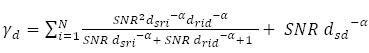
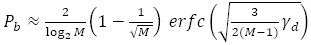
Fig.2 and Fig. 3 illustrate the BER for three relays when all located close to the source and close to the destination with á = 4, respectively. Using 4QAM modulation with AF relay will require an extra SNR to maintain the same BER but in all cases using relays always better than direct transmission. For instance, BER = 10-3 can be achieved at SNR ≈ 12 dB when single relay close to the source and SNR = 15 dB when single relay close to the destination. On the other hand, increasing number of relays will reduce the required SNR, for example, the same BER (10-3) can be geten at SNR ≈ 7 dB when two relays close to the source and SNR = 8 dB when two relays close to the destination.
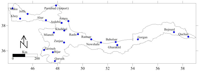 |
Figure 2: BER versus the SNR for three cases with direct link: using a single relay in red, using two relays in blue, and using three relays in black when all are located close to the source. |
 |
Figure 3: BER versus the SNR for three cases with direct link: using a single relay in red, using two relays in blue, and using three relays in black when all are located close to the destination. |
However, comparing the results in Figs.2 and 3 with that in Fig.1 reveals that the best location is at the center of the link between the source to the destination. The worst performance is when the place of the relay close to the destination with using 4QAM modulation.
To study effect of different propagation environment on BER, path loss exponent with different values will considered as a function of distance. Table 1 presents the results for three relays when the first, second and third relay are placed at the center with different SNR. Increasing the number of relays generally decreases the BER and further it decreases more when the relay is located at the center. The reason behind the reduction in BER is that path loss is function to distance and since placing relays will split the distance between source and the destination (dsd) into smaller distances. The BER in Eq.10 is function tofrom will associate with inverse relationships with á.
Conclusion
In this paper, BER of 4QAM for multiple AF relays in term of location between the source -destination with the direct link is investigated. Comparison between direct transmission and with using multiple relays in different locations the simulation results show that the best performance with lowest BER value may be obtained when relays are placed at the center of the link between the source and the destination. It also studies effects of the path loss for different propagation environment with three relays. The results show that the propagation environment has an effect on BER in which higher path loss exponent (i.e., harsh propagation environment) results in low BER if the relay exist in the system. When the signals propagate in NLOS environment with á is 5 and number of relays in the system are three, the lowest BER is 1 × 10⁻⁶ and decreasing more with increasing SNR.
References
- K. Loa, C. C. Wu, S.-T. Sheu, Y. Yuan, M. Chion, D. Huo, et al., IMT-advanced relay standards [WiMAX/LTE Update], IEEE Communications Magazine, 48(8), 2010, 40-48, DOI: 1109/MCOM.2010.5534586.
- A. Sendonaris, E. Erkip, and B. Aazhang, User cooperation diversity. Part I. System description, IEEE Transactions on communications, 51(11), 2003, 1927-1938,DOI: 1109/TCOMM.2003.818096
- M.-k. Chang and S.-y. Lee, Performance analysis of cooperative communication system with hierarchical modulation over Rayleigh fading channel, IEEE Transactions on Wireless Communications, 8(6), 2009, 2848 – 2852,DOI: 1109/TWC.2009.081077.
- H. A. Suraweera, G. K. Karagiannidis, and P. J. Smith, Performance analysis of the dual-hop asymmetric fading channel, IEEE Transactions on Wireless Communications, 8(6), 2009, 2783 -2788 ,DOI: 1109/TWC.2009.080420.
- I. Trigui, S. Affes, and A. Stephenne, On the performance of dual-hop fixed gain relaying systems over composite multipath/shadowing channels, in Vehicular Technology Conference Fall (VTC 2010-Fall), 2010 IEEE 72nd, 2010,1-5, DOI: 10.1109/VETECF.2010.5594177.
- A. Goldsmith, Wireless communications: Cambridge university press, 2005.
- T. S. Rappaport, Wireless communications: principles and practice vol. 2: Prentice Hall PTR New Jersey, 1996.
- K. R. Liu, Cooperative communications and networking: Cambridge university press, 2009.
- J. R. Hampton, Introduction to MIMO communications: Cambridge university press, 2013.
- K. G. Seddik, A. K. Sadek, W. Su, and K. R. Liu, Outage analysis of multi-node amplify-and-forward relay networks, in Wireless Communications and Networking Conference, 2006. WCNC 2006. IEEE, 2006, 1184-1188.
- P. Herhold, W. Rave, and G. Fettweis, Relaying in cdma networks: Pathloss reduction and transmit power savings, in Vehicular Technology Conference, 2003. VTC 2003-Spring. The 57th IEEE Semiannual, 2003, 2047-2051, DOI: 1109/VETECS.2003.1207185.
- M. Wu, D. Wübben, and A. Dekorsy, BER-based power allocation for amplify-and-forward and decode-and-forward relaying systems, in Smart Antennas (WSA), 2011 International ITG Workshop on, 2011, 1-8, DOI: 1109/WSA.2011.5741925.
- `M. Wu, D. Wübben, and A. Dekorsy, BER-based power allocation for decode-and-forwardrelayingwithm-qam constellations, in 7th International Wireless Communications and Mobile ComputingConference (IWCMC), 2011, 888-893, DOI: 10.1109/IWCMC.2011.5982664