Department of Computer Sciences, Sarvestan Branch, Islamic Azad University, Sarvestan, Iran
Corresponding author Email: isi.rahimkhani@gmail.com
Article Publishing History
Received: 12/03/2017
Accepted After Revision: 19/06/2017
As a results of technological progresses, wind power has appered as one of the most encouraging renewable energy sources. Due to severe Grid Code requirements, wind power plants (WPPs) should provide ancillaryservices such as fault ride-through and damping of power system oscillations to resembleconventional generation. Through an adequate selection of input–output signal pairs, WPPs can be effectivelyused to provide electromechanical oscillations damping. In this paper, implementation of the damping supplementary controllers of Wind Turbine (WT) based on Quantum Particle Swarm Optimization(QPSO) to damp low frequency oscillations in a weakly connected system is consideredd. Also, singular value decomposition (SVD)-based method is used to analysis and assess the controllability of the poorly damped electromechanical modes by WT different control channels. The problem of damping supplementary controller based WT system is formulated as an optimization problem according to the time domain-based objective function which is solved QPSO. The effectiveness of the proposed controllers on damping low frequency oscillations is checked through eigenvalue analysis.
Wind Turbine,Power System Stability, Quantum Particle Swarm Optimization, Supplemetary Damping Controller
Rahimkhani Z. Damping Controller Design for Wind Farms Based on Quantum Particle Swarm to Improve Power System Stability. Biosc.Biotech.Res.Comm. 2017;10(3).
Rahimkhani Z. Damping Controller Design for Wind Farms Based on Quantum Particle Swarm to Improve Power System Stability. Biosc.Biotech.Res.Comm. 2017;10(2). Available from: https://bit.ly/2Yob1OO
Introduction
Large interconnected ac systems have many well-known advantages. However, larger interconnected ac systems also increase the system complexity from the operation point of view, and might adversely decrease the system reliability.Steady state stability, lack of reactive power supply, voltage stability, electromechanical oscillations and transient stabilityare common problems that can happen in power systemsexpanded and transmit large amount of power over long distance transmission lines. Increasing power system complexity gives rise to low frequency oscillations in the range of 0.2–3.0 Hz. If not well damped, these oscillations may keep growing in magnitude until loss of synchronism results, (Hsu et al 1988 Shayeghi et al 2009, Zhang et al 2011).
In order to damp these power system oscillations and increase system oscillations stability, the installation of power system stabilizer (PSS) is both economical and effective.However, PSSs may adversely affect voltage profile, may result in leading power factor, and may not be able to suppress oscillations resulting from severe disturbances, especially those three-phase faults which may occur at the generator terminals(Banaei et al (2010).Flexible AC transmission systems devices,such as Static VAR Compensators (SVC), Thyristor Control Series Compensators (TCSC), Static Synchronous Compensators (STATCOM), and Unified Power Flow Controller (UPFC),are one of the recent propositions to alleviate such situations by controlling the power flow along the transmission lines and improving power oscillations damping(Banaei et al 2010, Shayeghi et al 2011).
The renewable energy systems and specially wind energy have been attracted due to the increasing concern about CO2 emissions. Wind power is rapidly increasing its presence in the power generation mix as one of the most promising renewable power source (WWEA (2011) (Ackermann (2005). For many countries wind power has already become an important electricity source, e.g., Denmark, Portugal, Spain and Germany. Due to this increment in wind power generation share, power systems stability and reliability may be affected (WWEA 2011 Tsili et al 2008). The characteristics of wind farms are substantially different from conventional power plants, such as hydraulic, nuclear or thermal (WWEA 2011 (Ackermann 2005). These facts have led to the establishment of grid codes regarding wind farm connection, and their integration in the grid (Hamdan 1999 MinisteriodeIndustriaTurismoyComercio 2006). According to these codes wind farms must comply with requirements including voltage sag ride through capability (Gomis-Bellmunt et al 2008), frequency regulation (Chen Blaajberg et al (2009), and active and reactive power regulation (ChenBlaajberg et al (2009).
In the future more wind farm contribution will be required by the system operators. The capability to damp power system oscillations will play an important role. There is a draft of the new Spanish grid code for wind power in which reference as already been made to inertia emulation and power oscillation damping (Gomis-Bellmunt et al (2008) (Chen,Blaajberg et al (2009).Different methods to select the best feedback signal to damp power oscillations have been discussed in (Hamdan (1999), but the case for WPPs has not been yet well covered. Recent research focuses on the best input–output signal pairs coupling based controllability and observability analyses such using singula value decomposition(SVD) (Li et al (2012).
Also a lead lag based QPSO controller is designed to damp low frequency oscillations. It is well known that traditional lead-lag damping controller structure is preferred by the power system utilities because of the ease of on-line tuning and also lack of assurance of the stability by some adaptive or variable structure methods (Panda et al(2008) (H Shayeghi et al (2009). Having several local optimum parameters for a lead-lag controller, using of traditional optimization approach is not suitable for such a problem. Thus, the heuristic methods as solution for finding global optimization are developed (Panda et al (2010) (Panda S (2009).Particle swarm optimization (PSO) is a novel population based metaheuristic, which utilize the swarm intelligence generated by the cooperation and competition between the particle in a swarm and has emerged as a useful tool for engineering optimization (Shayeghi et al 2008).This new approach features many advantages; it is simple, flexible, fast and can be coded in few lines. Also, its storage requirement is minimal. However, the main disadvantage is that the PSO algorithm is not guaranteed to be global convergent. In order to overcome this drawback and improve optimization synthesis, in this paper, a quantum-behaved PSO technique is proposed for optimal tuning of wind turbine based damping controller for enhancing of power systems low frequency oscillations damping.
In this paper a novel approach is presented to model power system supplied by wind turbine namelyPhillips-Heffronmodel based d-q algorithm in order to studying system dynamical stability.In addition, a block diagram representation is formed to analyze the systemstability characteristics.Also, singular value decomposition (SVD) is used to choose damping control signal which has most effect on damping the electromechanical (EM) mode oscillations. A very powerful tool commonly used for this purpose is Popov-Belevitch_Hautus(PBH) which can be used to evaluate the EM mode controllability of the PSS and the different inputs of system.A single machine infinite bus (SMIB) system equipped with a PSS and a wind turbine as a negative load. The problem of damping controllers design is formulated as an optimization problem to be solved using QPSO. The aim of the optimization is to search for the optimum controller parameter settings that maximize the minimum damping ratio of the system.
Fig.1shows a SMIB system equipped with a wind turbine. As it can be seen the infinite bus is supplied by AC transmission system. The wind turbine is modeled as a negative load which can tune active and reactive power.
Wind turbines tune the active power transferred to the network through an appropriate control of the generator-side converter. The purpose is to deliver the most active power from the wind turbine following an optimum wind power extraction [3-9]. Also, reactive power regulation is done through the control of the grid side converter. Because of the obtainability of active and reactive power measurements for converter control, these could be utilized potentially as control signals for damping controllers. For reaching goals of paper, the systeminputs (or control signals) could be the active and the reactive power transferred by wind turbine. Also, the outputs could be considered as the voltage magnitude and the voltage phase angle (Domı´nguez-Garcı´a JL et al (2012)).
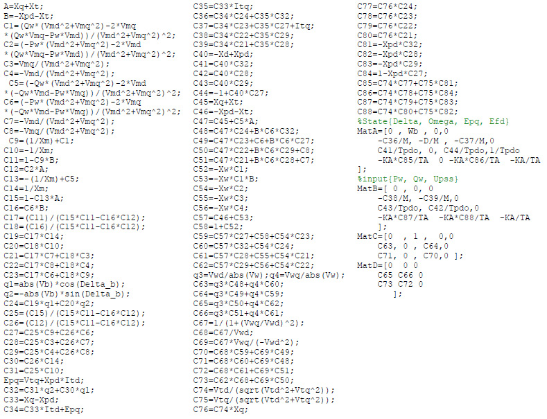
Power System Nonlinear Model
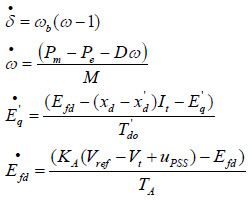
The non-linear model of the SMIB system of Fig.1 is:
![]()
![]()
where Pm and Pe are the input and output power, respectively; M and D the inertia constant and damping coefficient, respectively; ùb the synchronous speed; ä and ù the rotor angle and speed, respectively;
Eq, Efd´and Vt the generator internal, field and terminal voltages, respectively;Tdo´the open circuit field time constant;xd, xd ´and xq the d-axis, d-axis transient reactance, and q-axis reactance, respectively; KA and TA the exciter gain and time constant, respectively; Vref the reference voltage.Also, from Fig.1we have:
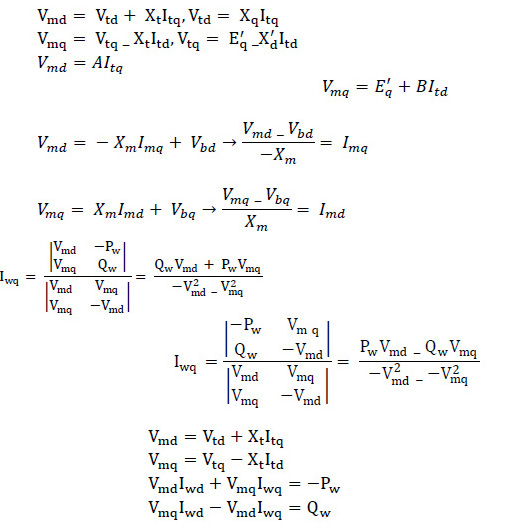
Also, we have:
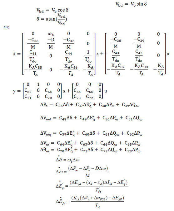
For the infinite bus:
Power System Linearized Model
By linearizing Eq (1)-(4)
Where:
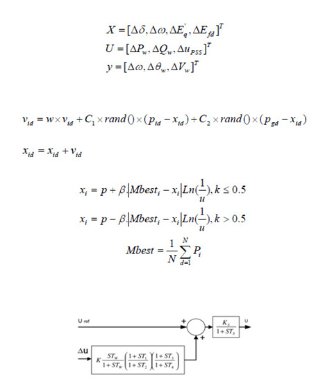
Using above equation we can obtain the state variable of the power system installed with the wind turbine to be(state space model):
And
Where ∆Pw, ∆Qw and uPSS are the linearization of the input control signals of the wind turbine and PSS output respectively.
PSO Versus Qpso
In a PSO system (H Shayeghi et al (2008)) (A. Awami et al (2007)) (H. Shayeghi et al (2010)), multiple candidate solutions coexist and cooperate simultaneously. Each solution candidate, called a “particle”, flies in the problem space (similar to the search process for food of a bird swarm) looking for the optimal position. A particle with time adjusts its position to its own experience, while adjusting to the experience of neighboring particles. If a particle discovers a promising new solution, all the other particles will move closer to it, exploring the region more thoroughly in the process.
PSO starts (Panda S et al (2008)) with a population of random solutions ‘particles’ in a D-dimension space. The ith particle is represented by Xi = (xi1, xi2,…, xiD). Each particle keeps track of its coordinates in hyperspace, which are associated with the fittest solution it has achieved so far. The value of the fitness for particle i(pbest) is also stored as Pi = (pi1, pi2,…, piD). The global version of the PSOkeeps track of the overall best value (gbest), and its location, obtained thus far by any particle in the population (Li Y et al (2012)) (Panda S et al (2008)). PSO consists of, at each step, changing the velocity of each particle toward its pbest and gbest according to following equations:
Where, pid = pbest and pgd = gbest
PSO algorithm is as follow:
Step. 1: Initialize an array of particles with random positions and their associated velocities to satisfy the inequality constraints.
Step. 2: Check for the satisfaction of the equality constraints and modify the solution if required.
Step. 3: Evaluate the fitness function of each particle.
Step. 4: Compare the current value of the fitness function with the particles’ previous best value (pbest). If the current fitness value is less, then assign the current fitness value to pbest and assign the current coordinates (positions) to pbestx.
Step. 5: Determine the current global minimum fitness value among the current positions.
Step. 6: Compare the current global minimum with the previous global minimum (gbest). If the current global minimum is better than gbest, then assign the current global minimum to gbest and assign the current coordinates (positions) to gbestx.
Step. 7: Change the velocities according to eq. (20).
Step. 8: Move each particle to the new position according to eq. (21) and return to Step 2.
Step. 9: Repeat Step 2–8 until a stopping criterion is satisfiedor the maximum number of iterations is reached.
The main disadvantage is that the PSO algorithm is not guaranteed to be global convergent (H. Shayeghi et al (2010)). The dynamic behavior of the particle is widely divergent form that of that the particle in the PSO systems in that the exact values of xi and vi cannot be determined simultaneously. In quantum world, the term trajectory is meaningless, because xi and vi of a particle cannot be determined simultaneously according to uncertainty principle. Therefore, if individual particles in a PSO system have quantum behavior, the PSO algorithm is bound to work in a different fashion. In the quantum model of a PSO called here QPSO, the state of a particle is depicted by wave function W(x, t) instead of position and velocity (Coelho LS (2008)) (H.Shayeghi et al(2010)). Employing the Monte Carlo method, the particles move according to the following iterative equation:
Where u and k are values generated according to a uniform probability distribution in range (Coelho LS (2008)), the parameter â is called contraction expansion coefficient, which can be tuned to control the convergence speed of the particle. In the QPSO, the parameter â must be set as â < 1.782 to guarantee convergence of the particle (H. Shayeghi et al (2010)).Where Mbest called mean best position is defined as the mean of the pbest positions of all particles. i.e.:
The procedure for implementing the QPSO is given by the following steps (Coelho 2008 and Shayeghi et al (2010):
Step 1: Initialization of swarm positions: Initialize a population (array) of particles with random positions in the n-dimensional problem space using a uniform probability distribution function.
Step 2: Evaluation of particle’s fitness: Evaluate the fitness value of each particle.
Step 3: Comparison to pbest (personal best): Compare each particle’s fitness with the particle’s pbest. If the current value is better than pbest, then set the pbest value equal to the current value and the pbest location equal to the current location in ndimensional space.
Step 4: Comparison to gbest (global best): Compare the fitness with the population’s overall previous best. If the current value is better than gbest, then reset gbest to the current particle’s array index and value.
Step 5: Updating of global point: Calculate the Mbest using eq.(24).
Step 6: Updating of particles’ position: Change the position of the particles according to Eq. (23), where c1 and c2 are two random numbers generated using a uniform probability distribution in the range [0, 1].
Step 7: Repeating the evolutionary cycle: Loop to step 2 until a stop criterion is met, usually a sufficiently good
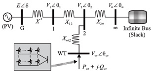 |
Figure |
PSS and Wind Turbine Damping Controller
The damping controller is designed to produce an electrical torque in-phase with the speed deviation according to phase compensation method. The PSS structure to be considered is the very widely used lead-lag controller, whose transfer function is [28]:
The wind turbine damping controllers are of the structure shown in Fig. 2 which u can be U = [∆Pw, ∆Qw]T. It includes gain block, signal-washout block and lead–lag compensator. The parameters of the damping controller are obtained using QPSO algorithm.
 |
Figure 2 |
Wind Turbinedamping Controller Design Using Qpso
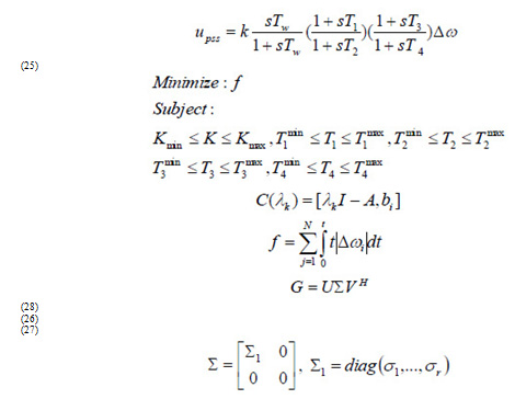
To obtain optimal parameters, this paper employs QPSO (Coelho LS (2008)) to enhance optimization synthesis and find the global optimum value of fitness function. The objective function (which must be minimized) is defined as follows (Shayeghi et al 2006):
Where t is the time range of simulation and N is the total number of operating points for which the optimization is carried out. The design problem can be formulated as the following constrained optimization problem, where the constraints are the controller parameters bounds (Awami et al (2007):
Typical ranges of the optimized parameters are [0.01–100] for K and [0.01–1] for T1, T2, T3 and T4. The proposed approach employs QPSO algorithm to solve this optimization problem and search for an optimal or near optimal set of controller parameters.
Controllability Measurement
Based On Svd
Controllability shows how the state variables describing the behavior of a system can be influenced by its inputs. More accurately, the dynamical system
x = Ax + Bu
or the pair (A,B) is said to be state controllable if, for any initial state x(0) = x0 any time t1 > 0 and any final state x1 there exist an input u(t) such that x(t1) = x1. Otherwise the system is said to be state uncontrollable.
In damping of power oscillations, it is necessary to detemine controllability for specific eigenvalues (electromechanical mode). A very powerful tool commonly used for this purpose is Popov-Belevitch_Hautus(PBH) test which is described as below.It includes in evaluating the rank of matrices:
Which ëk is the kth eigenvalue of the matrix A, I is the identity matrix, bk is the column of B corresponding to ith input ui. The mode ëk of linear system in state space form is controllable if matrix C(ëk) has full row rank.The rank of matrices can be evaluated by their singular values. The singular values are defined as below:
If is a m × n complex matrix, then there exist unitary matrices U and V with dimensions of m × m and n × n, respectively, such that:
(29)
Where
With ó1 ≥ ór ≥ 0 where r = min{m,n} and ó1,…, ór are the singular values of G.
The minimum singular value ór represents the distance of the matrix G from all the matrices with a rank of r – 1 [32]. This property can be used to quantify modal controllability and observability [32, 33]. The matrix H (and J) can be written as H = [h1 h2 h3 h4] where hi is a column vector corresponding to the ith input. The minimum singular value, óminof the matrix [ëI – A, hi] indicates the capability of the ith input to control the mode associated with the eigenvalue ë. Actually, the higher ómin, the higher the controllability of this mode by the input considered. As such, the controllability of the EM mode can be examined with all inputs in order to identify the most effective one to control the mode. Thus, the choice of input through the PBH test is done by selecting those with the largest of the minimum singular values of matrices C(ëk).
Simulation Results
Power system information is given in appendix A. Constant coefficients in modelling are calcuated according informations which given in appendix B. In this paper, we consider ∆ù (rotor speed deviation) asoutputs andthree inputs which are U = [∆Pw, ∆Qw, ∆uPSS]T i.e. active power and reactive power of wind turbine and finally PSS input. Selecting an affective coupling between inputs-ouput for damping oscillation of the power system is one of the most imporatant goals of this paper. Following section consider this topic.
Controllability and Observability Measure By Using Pbh Test
SVD based on PBH is employed to measure the controllability of the electromechanical mode (EM) mode from each of the three inputs: U = [∆Pw, ∆Qw, ∆uPSS]T. The minimum singular value ómin is estimated over a wide range of operating conditions. For SVD analysis, Pe ranges from 0.01 to 1.5Pu and Qe = [-0.4,0,0.4]. At each loading condition, the system model is linearized, the EM mode is identified, and the SVD-based controllability and observability measure is implemented. For comparison purposes, the minimum singular value for all inputs at Qe = 0.4Pu is shown in Fig. 3. From these figures, the following can be noticed:
- EM mode controllability via ∆Pw, ∆Qw is almost higher than the ∆uPSS.
- The capabilities of ∆Pw, ∆Qw to control the EM mode is almost equal.
- EM mode observability via ∆Vw, ∆èwis almost higher than the ∆ù.
Using Qpso To Obtain Parameters Of Supplementary Controllers
The QPSO algorithm is used to obtain the optimal parameter settings of each of the supplementary controllers so that the objective function is optimized.The final parameters are given in table 1.
| Table 1: Parameters of supplemetary controller designed by QPSO | |||
| PSS | ∆Pw | ∆Qw | |
| k | -0.3572 | 3.23 | -30.33 |
| T1 | 0.32 | 2.01 | 0.042 |
| T2 | 0.012 | 0.027 | 0.041 |
| T3 | 5.1 | 9.1 | 0.1 |
| T4 | 0.22 | 3.2 | 0.073 |
These supplementary controllers are used by wind turbine system in different loading condition (Table 2).
| Table 2: System condition | |||||
| Qe | Pe | Vt | Qe | Pe | Operating Condition |
| 0 | 0.2 | 1 | 0.015 | 1 | ë1 (Nominal) |
| 0.1 | 0.4 | 1 | 0.4 | 1.2 | ë2 (Heavy) |
Responses of system to a mechanical power change (∆Pm = 0.05) in synchronous generator as a disturbance for system are shown in Fig.4.5.
 |
Figure 3 |
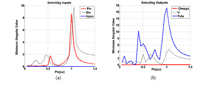 |
Figure 4 |
 |
Figure 5 |
Conclusion
In this paper, SVD has been employed to evaluate the electromechanical mode controllability to PSS and the wind turbine control signals. It has been shown that the electromechanical mode is most powerfully controlled via ∆Pe for a wide range of loading conditions. Also, the quantum-behaved particle swarm optimization algorithm has been successfully applied to the robust design of wind turbine based damping controllers. The effectiveness of the proposed wind turbine controllers for improving transient stability performance of a power system are demonstrated by a weakly connected power system subjected to disturbance.
APPENDIX A
The test system parameters are (all in pu):
APPENDIX B
Coefficients are:
References
- Ackermann T (2005), Wind power in power systems. Wiley.
- Awami, A., Y.Abdel-Magid, M.A.Abidi (2007), “Particle-swarm-based approach of power system stability enhancement with unified power flow controller”, Electrical power and energy systems 29, pp251–259.
- Banaei, M., N.Taheri (2010),“An adaptive neural damping controller for HVDC transmission systems, Euro”, Trans. Electr. Power, DOI: 10.1002/etep.485.
- Chen Z, Blaajberg F (2009), “Windfarm a farmsourceinfuturepowersystems”, Renewable andSustainableEnergy Review, pp 1288–1300.
- Coelho LS (2008). “A quantum particle swarm optimizer with chaotic mutation operator”, Chaos Soliton Fractals, pp1409–1418.
- Domı´nguez-Garcı´a JL,RogersD,Ugalde-LooC,LiangJ,Gomis-BellmuntO (2012),“Effect of non-standard operating frequencies on the economic cost of offshore Acnetworks”, RenewableEnergy, pp267–280.
- Flourentzou N, Agelidis VG, Demetriades GD(2009), “VSC-based HVDC power transmission systems: an overview”, IEEE Trans Power Electron, pp 592–602.
- FoxB FlynnD, Bryans L, Jenkins N, Milborrow D, O’Malley M, et al (2007), “Wind power integration: connection and system operational aspects”, TheInstitu- tion of Engineering and Technology.
- Gomis-BellmuntO,Junyent-FerreA,SumperA,Bergas-JaneJ.Ride (2008), “through control of a doubly fed induction generator under unbalanced voltage sags. IEEE Transactions on Energy Conversion 21036–1045.
- Hamdan A (1999),“An investigation of the significance of singular value decomposition in power system dynamics”, Int J Electr Power Energy Syst, pp21:417–24.
- Heniche A, Kamwa I (2008),“Assessment of two methods to select wide-area signals for power system damping control”, IEEE Trans Power Syst, pp572–81.
- Li Y, Rehtanz C, Rüberg S, Luo L, Cao Y (2012),“Assessment and choice of input signals for multiple HVDC and facts wide-area damping controllers”, IEEE Trans Power Syst, pp 1969–77.
- Licéaga-Castro E, Licéaga-Castro J, Ugalde-Loo CE (2005),“Beyond the existence of diagonal controllers: from the relative gain array to the multivariable structure function”, In: Proceedings of the 44th IEEE conference on decision and control and 2005 European control conference, pp 7150–6.
- Magaji N, Mustafa M (2011),“Optimal location and signal selection of UPFC device for damping oscillation”, Int J Electr Power Energy Syst, pp 1031–42.
- MinisteriodeIndustria Turismoy Comercio (2006):SecretariadeEstadode Energı´a. Procedimientos deoperacio´n 12.3.
- Panda S (2009),“Multi-objective non-dominated shorting genetic algorithm-II for excitation and TCSC-based controller design”, J ElectrEng, pp 87–94.
- Panda S (2011),“Differential evolution algorithm for SSSC-based damping controller design considering time delay”, J Franklin Inst, pp 903–26.
- Panda S, Prasad Padhy N (2008), “Comparison of particle swarm optimization and genetic algorithm for FACTS based controller design”, Appl Soft Comput, pp 1418–27.
- Panda S, Swain SC, Rautray PK, Mallik R, Panda G (2010),“Design and analysis of SSSCbasedsupplementary damping controller”,Simulat Model PractTheor, pp 199–213.
- Shayeghi H, HA Shayanfar, S Jalilzadeh, A Safari (2009),“A PSO based unified power flow controller for damping of power system oscillations”, Energy Convers Manage50, pp2583–92.
- Shayeghi, H., HAShayanfar, A Jalili (2006),“Multi stage fuzzy PID power system automatic generation controller in deregulated environments”, Energy Convers Manage, pp 47:2829–45.
- Shayeghi, H., A.Safari, H.A.Shayanfar (2011), “PSS and TCSC damping controller coordinated design using PSO in multi-machine power system”, Energy conversion and management 51, pp 2930–2937.
- Shayeghi, H., H.A.Shayanfar, S.Jalilzadeh, A.Safari (2009), A PSO based unified power flow controller for damping of power system oscillations, Energy conversion and management 50, pp 2583–2592
- Shayeghi,H., AJalili, HA Shayanfar (2008),“Multi-stage fuzzy load frequency control using PSO”, Energy Convers Manage, pp2570–80.
- Shayeghi,H., H.A.Shayanfar, S.Jalilzadeh, A.Safari (2010), “Tuning of damping controller for UPFC using quantum particle swarm optimizer”, Energy conversion and management 51, pp 2299–2306
- Skogestad S, Postlethwaite I (2007),“Multivariable feedback control – analysis and design. Chichester (UK)”, John Wiley & Sons.
- TsiliM,PatsiourasC,PapathanassiouS (2008), “Grid code requirements for large wind farms: a review of technical regulations and available wind turbine technologies”, In: Proceedings of the European wind energy conference& exhibition (EWEC’08).
- WWEA (2011), World wind energy report 2011.
- Y. Hsu., L. Wang (1988), “Damping of a parallel ac-dc power systemusing pid power system stabilizers and rectifier current regulators”,IEEE Trans. Energy Conversion 3, pp 540–547.
- Zhang L, Harnefors L, Nee H-P (2011),” Interconnection of two very weak ac systems by VSC-HVDC links using power-synchronization control”, IEEE Trans Power Syst, pp 344–55.
- Zhang Y, Bose A (2008),“Design of wide-area damping controllers for interarea oscillations”, IEEE Trans Power Syst, pp 23(3):1136–43.
- Zhang, L., L.Harnefors, H.Peter (2011), “Interconnection of two very weak AC systems by VSC-HVDC links using power-synchronization control”, IEEE transaction on power systems.