1*Dr.N.G.P. Institute of Technology, Coimbatore, India
2,4Department of Computer Science, College of Engineering & Technology, Dambi Dollo University, Oromia Region, Ethiopia
3, Department of Information Technology, College of Engineering & Technology, Dambi Dollo University, Oromia Region, Ethiopia
5Department of EEE, Roever Engineering College, Perambalur, India
Corresponding author email: drkssece@gmail.com
Article Publishing History
Received: 04/11/2020
Accepted After Revision: 20/12/2020
Calculation of the numerical values of the depth of cancer tissues have been presented in the cancerous organs. In this work we have developed a wideband antenna to detect the cancerous organs. An EF shaped wideband antenna with 2×2 grid pattern has been designed with its geographical coordinates by mathematical modelling; simulated by Advanced Design Simulator (ADS) using Moments of Methods (MoM); fabricated their design in the form of a prototype using Microwave Monolithic Integrated Circuits (MMIC); and analysed by Agilent N99917A Microwave Analyser, which has been represented in this primary goal of research. It comprises a compact dimensional of 18.64×17.92×1 mm3. It includes the 2×2 array pattern with four EF shaped radiating slots, which printed on the 1-millimetre dielectric thickness of FR4 material and the conductive ground plane. It has been delivered at 5.417 GHz operational frequency, which covers the wideband spectrum of 4.89 GHz to 6 GHz. Furthermore, it has a wideband antenna, a low-profile structure with four numbers of radiating slots. These wideband antennas have been implemented for breast cancer detection application, which is represented by the secondary delivery of research.
These wideband antenna with human breast equivalent dielectric model under existing Debye testbeds. These wideband antennas have impressed on the coupling materials, which act as the coupling medium. They have provided better scattering results than air medium. These coupling materials have presented higher and lower dielectric strengths respectively. The average of scattered responses has gathered on it. It has determined the depth of cancerous tissues presented in the cancerous organ with the help of velocity of propagation, the distance between the cancerous organ and transceiver antenna, dielectric strength and travelling time of scattered responses respectively. Therefore, these scattered responses have been obtained from the cancerous organs under Debye testbed. Hence, the numerical value of depth and spreading the coverage of depth in cancerous organ is validated under existing Debye testbeds.
Breast Cancer, 2×2 Array pattern; EF shaped Prototypes; Microstrip Patch antenna.
Sakthisudhan K, Saravanan V, Lawrence T. S, Ushuri K. T, Kumar R. S. Breast Cancer Detection: Analysis by Wideband Antennas. Biosc.Biotech.Res.Comm. 2020;13(4).
Sakthisudhan K, Saravanan V, Lawrence T. S, Ushuri K. T, Kumar R. S. Breast Cancer Detection: Analysis by Wideband Antennas. Biosc.Biotech.Res.Comm. 2020;13(4). Available from: https://bit.ly/35r8vx1
Copyright © Sakthisudhan et al., This is an Open Access Article distributed under the Terms of the Creative Commons Attribution License (CC-BY) https://creativecommons.org/licenses/by/4.0/, which permits unrestricted use distribution and reproduction in any medium, provide the original author and source are credited.
INTRODUCTION
The microwave spectrum has been used during past twenty decades in medical, industrial and scientific applications. The microwave imaging is one of the most suitable breast cancer detection techniques. Its main objective is the hypothesis that the dielectric properties, electrical properties, impedance matching, conductivity, permittivity of the cancerous breast’s tumor tissues are slightly different from the normal breast tissues and the cancerous organ’s tissues. Microwave frequencies are millimetre wavelengths of the electromagnetic spectrum. The MI system provided the non-ionizing and non-invasive approaches and showed reasonable penetration in the breast tissue surrounding of breast organ. The microwave imaging techniques were used in one pair of antennas (transmitter, receiver antenna). The transmitter transmitted the microwave signals to the breast and the internal tissues surrounding it.
The receiver side scattered signals were reflected on it, which were gathered by the receiver antenna. The cancerous (malignant tumors) and normal breast tissues have different dielectric permittivity and conductivity properties. Microwave signal is reflected by the cancerous tissue and the scatter signal will collect from the body as differently. Microwave signals through diagnosis trials detected a malignant tumour of 5-10 millimetre range with an accuracy of 85%. Moreover, the ultra-wideband microwave imaging systems have been used to examine the breast cancer diagnosis, (Meaney et al., 2000, Fear et al., 2002, Gibbins et al., 2009, Sakthisudhan et al., 2020).
A wideband antenna has been operated under 4.5 GHz-10 GHz microwave frequencies. It was designed by cavity –backed patch antenna with a 3D array pattern which was replaced by monopole antennas with a 2D array pattern. The microwave imaging system, focusing on the following challenges and issues were discussed as, i)Ultra-Wide-Band antennas, ii) Compact size, iii) Steerable antennas, iv) Interference rejection factors,and v) Improved radiation efficiency. Chu Yu et al (Yu et al., 2008) examined a prototype model for Microwave Imaging systems.
This system consisted of one pair of dipole antennas to avoid mutual coupling losses between two ports. This proposed system can effectively detect the dielectric size of object is 5 mm at 1.74 GHz imaging frequency. Similarly, the various microstrip patch antennas of surveys have demonstrated the various test beds such as, Dipole Antennas; Dielectric Resonator Antennas; Patch antennas; Slot antennas; Vivaldi antennas; Horn antennas and MEMS Micro electro mechanical systems -steerable antennas (Woten and El-Shenawee, 2008, Shi et al., 2009, Amineh et al., 2009, Huang and Kishk, 2009, Gibbins et al., 2009, Al-Joumayly et al., 2010, Bourqui et al., 2010, Hutchings and El-Shenawee, 2010, Amineh et al., 2010, See et al., 2012, Sakthisudhan et al., 2020).
The Microwave Imaging system, coupling materials are mandatory to reduce the mismatching between the antenna systems and the breast tissue. Transverse. The comparative study of slot antennas and stacked antennas were used in the imaging systems (Sakthisudhan et al., 2020).In this research the microstrip patch antenna design and fabrication have been found suitable for cancerous diagnosis applications.
MATERIAL AND METHODS
A 2×2 array pattern of EF shaped Microstrip patch antenna has been illustrated in Figure 1. The proposed prototype is to be required the following design parameters, such as, selection of 5 GHz resonator frequency; FR4 dielectric substrate with dielectric constant is 4.6; and thickness of dielectric layer is 1mm. It consists of conductive strip of 12.64×17.9 mm2with mounted on 1 mm dielectric layer thickness. Therefore, it achieves a compact design of 18.64×24.9×1 mm3dimensional area.
Figure 1 a): Geometric coordinates (units in milimeter); b) simulation snapshot & c) fabricated prototypes of EF Shaped with 2×2 grid pattern.
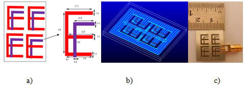
A proposed design is designed by mathematical modelling equation. The excitation port is etched on the ([a] matrix element) a23EF shaped element of the array pattern via 50Ω of RF-SMA connectors. The proposed structure is fabricated with 4.6 dielectric constant with 1 mm thickness of FR4 material, mounted on the conductive ground plane strip via Surface Mount Adaptor (SMA) connector. The SMA connector is measured by Microwave Analyzer (Agilent N99917A) and this testing results are reliable and compared with the simulated prototype.(Sakthisudhan et al 2016, 2020)
Figure 2: Proposed prototypes impressed in coupling materials a) higher & b) conductive medium
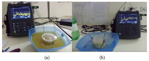
A delivery of secondary research, the proposed prototypes with dielectric phantom model has been examined the scattered signal, which is illustrated in Figure 2. The dielectric phantom model consists of human equivalent model. It consolidated the different biological contents, which dielectric strengths are plotted in Table 1. Hence, these test bed have delivered the four different stages of results, they are early stage; minor stage, growing stage and major stages respectively.
Table 1. Contents of breast phantom model
| S.No | Dielectric
Materials |
Biological Breast Contents | Standard dielectric strength | Equivalent dielectric strength | Dielectric strength examined by measurements |
| 1. | Human Breast Model | Cancerous Tissue | 42-45 | Coal Piece | 43 |
| 2. | Breast Tissue | 27-35 | Wheat Flour | 27.654 | |
| 3. | Skin Layer | 36-42 | Glycerin | 35.129 | |
| 4. | Blood Components | 50-60 | Big Sugar | 53.2 | |
| Sugar | 51.5 | ||||
| 5. | Textile Woven Materials | Cotton Woven | 3.9-7.5 | Cotton | 4.83 |
| 6. | Polyester Woven | 2.8-4.5 | Polyester | 3.8 | |
| 7. | Coupling Materials | Glycerin | 43 | Glycerin | 40.41 |
| 8. | Vegetable Palm Oils | 3.75 | Vegetable Palm Oils | 3.87 |
RESULTS AND DISCUSSION
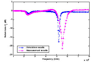
The comparison of the fabricated MPA prototype with the simulated MPA design is shown in Figure 3. The return loss of 17.473 dB has been achieved at a resonant of 5.156 GHz and coverage of wide band of 4.8 to 6 GHz in the simulation structure. The return loss of 21.274 dB has been obtained at a resonance of 5.417 GHz, coverage of 4.89 to 5.3 GHz in the fabricated MPA prototypes. A comparison of the proposed MPA with the existing MPAs is listed in Table 2. MPAs require the UWB band of frequencies and ISM application standards. The fabricated MPAs results are justified with that of the simulated MPAs design and has improved FBW than the simulated MPA design. Hence, it is called as wideband prototypes (Sakthisudhan et al 2020).
Table 2. Performance study of proposed 2×2 Array of EF Microstrip slots and Existing slots
| S. No | Antenna Parameters |
2×2 Array of EF Microstrip slots | Existing Microstrip slots | |||||
| Simulation design | Fabricated prototype | (Denidni et al., 2008) | (Hazra et al., 2013) | (Liu et al., 2010) | (Liu et al., 2011) | (Archevapanich et al., 2007)
|
||
| 1. | Shape of Patch Strips | 2×2 Array of EF Shaped | E Shaped | P Shaped | Inverted L Shaped | Inverted L Shaped | E Shaped | |
| 2. | Resonance fr (GHz) | 5.156 | 5.417 | 5.8 | 2.45 | 2.42, 5.2 | 2.3, 3.6, 5.04 | 2.46, 5.3 |
| 3. | Return Loss S11 (dB) | 17.473 | 21.274 | <10 | 17.5 | <10 | >20 | 40.31 |
| 4. | Reflection Coefficient (Г) | 0.13 | 0.09 | 0.316 | 0.133 | 0.316 | 0.1 | 0.1 |
| 5. | VSWR Ratio | 1.31 | 1.19 | 1.92 | 1.3 | 1.92 | 1.22 | 1.22 |
| 6. | Reflected Power (%) | 1.69 | 0.81 | 9.9 | 1.8 | 9.9 | 1 | 1 |
| 7. | Reflected Power (dB) | -17.7 | -20.9 | -10.03 | -17.45 | -10.03 | -20.08 | -20.08 |
| 8. | Mismatch Loss (dB) | 0.08 | 0.03 | 0.45 | 0.08 | 0.45 | 0.04 | 0.04 |
| 9. | Non Reflected Power- dB | 0.9665 | 0.9838 | 0.9 | 0.98 | 0.9 | 0.99 | 0.99 |
| 10. | Bandwidth Coverage GHz | 4.8 to 6 | 4.89 to 6 | 4.8-6 | 2.35-2.25 | 2.34-2.55
4.8-7.2 |
2.14-2.52
2.82-3.74 5.15-6.02 |
2.4-2.52
4.82-6.32 |
| 11. | Fractional BW (%) | 23.27% | 20.49% | 20.69 | 4.08 | 8.67,46.1 | 16.5, 25.56, 17.3 | 4.87
28.3 |
| 12. | Antenna Q Factor | 4.3 | 10.8 | 4.83 | 24.5 | 97.1 | 5.79 | 3.53 |
| 13. | Dimension of Design (mm3) | 18.7×23.9×1 | 15x25x5.78 | 110×158.5×1.52 | 25x30x05 | 20×30 | 27×17.3×1.575 | |
Figure 3: Comparison of fabricated & simulated prototypes
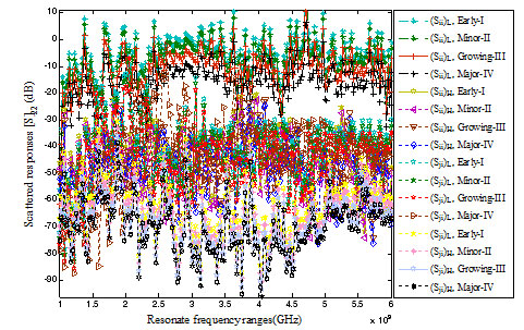
These proposed microstrip slots have been evaluated by the Existing Debye test bed setup, illustrated in Figure 2 (a & b).It consists the pair of transreceiver antenna with human’s dielectric equivalent breast model. These scattered responses have examined under lower and higher coupling medium respectvely. Since, these proposed slots have impressed in these coupling medium. Figure 4 has gathered scattered signals from different resolution stages under Debye test beds. Finally, these results have analysed and segregated with dielectric equivalent of healthy organs. These results have described the early, minor, growing and major stages of cancerous organ respectively. Therefore, the spreading cancer tissues, depth has calculated in the Table 4.
Table 4. Analysis of tumor characteristics of microstrip slot of EF with an Existing Debye Test Beds
| Proposed MPAs Based Debye Test Beds | Category of Screening stages
|
Depth of tumor
At Major Stage Frequency fmajor(GHz) |
Depth of tumor
At Early Stage Frequency fearly (GHz) |
Travelling Time (ns) | Proposed microstrip antennas | (Fear et al., 2002) Analyzed in Existing Debye Test Beds Parameters | Physical Distance Between the Tumor with MPAs
(cm) |
|||||
| Dielectric Strength of Tumor | Velocity of Propagation
(mm/s) |
Depth of Tumor by Numerical Analysis (mm) | Dielectric Strength of Tumbeen or | Velocity of Propagation
(mm/s) |
Depth of Tumor by Numerical Analysis (mm) | |||||||
| Early-I
1cm |
5 | 3.4 | 0.625 | 48.5 | 4.3×10¹⁰ | 53.75 | 9 | 1011 | 125 | 129.8 | ||
| Minor-II
2cm |
5 | 3.45 | 0.65 | 48.5 | 4.3×10¹⁰ | 55.9 | 9 | 1011 | 130 | 127.4 | ||
| Growing-III
2.5 cm |
5 | 3.5 | 0.667 | 48.5 | 4.3×10¹⁰ | 57.36 | 9 | 1011 | 133.4 | 109.2 | ||
| Major-IV
3 cm |
4.99 | 3 | 0.503 | 48.5 | 4.3×10¹⁰ | 43.26 | 9 | 1011 | 100.6 | 110.4 | ||
|
|
(Kiruthika and Sharma, 2011) | 5 | 3.4 | 0.625 | 21.3 | 6.5×10¹⁰ | 81.25 | 9 | 1011 | 125 | 129.8 | 129.8 |
| 5 | 3 | 0.503 | 21.3 | 6.5×10¹⁰ | 65.39 | 9 | 1011 | 100.6 | 127.4 | 127.4 | ||
| 5 | 3.45 | 0.65 | 21.3 | 6.5×10¹⁰ | 84.5 | 9 | 1011 | 130 | 110.4 | 110.4 | ||
| (Salvador and Vecchi, 2009) | 5 | 3.4 | 0.625 | 20 to 40 | 5.3×10¹⁰ | 66.25 | 9 | 1011 | 125 | 129.4 | 129.4 | |
| 4.99 | 3 | 0.503 | 60 to 80 | 3.1×10¹⁰ | 31.186 | 9 | 1011 | 100.6 | 109.2 | 109.2 | ||
Figure 4: Scattered Signals have gathered by Existing Debye Test-beds
CONCLUSION
A 2×2 grid pattern with EF shaped fabricated prototypes has been demonstrated and validated by Network Analyzer in this research. Moreover, these prototypes have been compared with the existing prototypes. It has delivered the resonant frequency of 5.417 GHz, wide band spectrum of bandwidth 4.89 to 6 GHz. The different tumor resolution characteristics have been demonstrated under the existing Debye model. Hence, these data have provided the clinical diagnosis of the breast cancer. Furthermore, these analyses have offered the depth of cancerous organ under different resolution stages, which can be used suitably by radiology professionals.
REFERENCES
Al-Joumayly, M.A. Aguilar, S.M. Behdad, N. Hagness, S.C. (2010) Dual-band miniaturized patch antennas for microwave breast imaging IEEE antennas and wireless propagation letters, 9, pp. 268-271.
Amineh, K.R. Trehan, A. Nikolova, N. K. (2009) TEM horn antenna for ultra-wide band microwave breast imaging Progress In Electromagnetics Research, 13, pp. 59-74.
Amineh, R.K. Ravan, M. Trehan, A. Nikolova, N.K. (2010) Near-field microwave imaging based on aperture raster scanning with TEM horn antennas, IEEE Transactions on Antennas and Propagation, 59, pp.928-940.
Archevapanich, T. Nakasuwan, J. Songthanapitak, N. Anantrasirichai, N. Wakabayashi, T. (2007) E-shaped slot antenna for WLAN applications, Piers online, 3, pp. 1119-1123.
Bourqui, J. Okoniewski, M. Fear, E.C. (2010) Balanced antipodal Vivaldi antenna with dielectric director for near-field microwave imaging IEEE Transactions on Antennas and Propagation, 58, pp. 2318-2326.
Denidni, T. A. Hassaine, N. Rao, Q. (2008) Broadb and high-gain E-shaped microstrip antennas for high-speed wireless networks Progress In Electromagnetics Research, 1, pp.105-111.
Fear, E. C. Li, X. Hagness, S. C. Stuchly, M.A. (2002) Confocal microwave imaging for breast cancer detection: Localization of tumors in three dimensions’, IEEE Transactions on biomedical engineering, 49, pp. 812-822.
Gibbins, D. Klemm, M. Craddock, I. J. Leendertz, J. A. Preece, A. Benjamin, R. (2009) A comparison of a wide-slot and a stacked patch antenna for the purpose of breast cancer detection IEEE transactions on antennas and propagation, 58, pp.665-674.
Hazra, R. Ghosh, C. K. Parui, S. (2013) P-shaped Wearable Antenna for ISM band at 2.45 GHz International Journal of Innovation and Applied Studies, ISSN 2028-9324.
Huang, W. Kishk, A. (2009) Compact dielectric resonator antenna for microwave breast cancer detection’, IET microwaves, antennas & propagation, 3, pp.638-644.
Hutchings, D. A. El-Shenawee, M. (2010) Fabrication of broadband MEMS antennas and application to target detection’, IEEE Antennas and Propagation Society International Symposium, IEEE, pp. 1-4.
Kiruthika, N. Sharma, S. (2011) An investigation on microwave breast cancer detection by ultra-wideband microstrip slot antennas IEEE Int Symposium Antennas Propagat, pp. 3385-3388.
Liu, W.C. Wu, C.M. Chu, N.C. (2010) A compact CPW-fed slotted patch antenna for dual-band operation’, IEEE Antennas and Wireless Propagation Letters, 9, pp. 110-113.
Liu, W.C. Wu, C.M. Dai, Y. (2011) Design of triple-frequency microstrip-fed monopole antenna using defected ground structure IEEE transactions on antennas and propagation, 59, pp. 2457-2463.
Meaney, P.M. Fanning, M.W. Li, D. Poplack, S. P. Paulsen, K.D. (2000) A clinical prototype for active microwave imaging of the breast IEEE Transactions on Microwave Theory and Techniques, 48, pp.1841-1853.
Sakthisudhan, K. Saravana Kumar, N. (2016) Certain Study on Improvement of Bandwidth in 3 GHz Microstrip Patch Antenna Designs and Implemented on Monostatic Radar Approach for Breast Cancer Diagnosis in Microwave Imaging System Journal of Circuits, Systems and Computers, 25, 1650006.
Sakthisudhan, K. Bommi, R.M. Sankar Ganesh, S. Nandhakumar, S. Senthilkumar, R. (2020) Wideband Antennas on Glass Reinforced Epoxy Materials Materials Today: Proceedings, Elsevier Publication, https://doi.org/10.1016/j.matpr.2020.09.388
Sakthisudhan, K. Amirthalakshmi, T.M. Sankar Ganesh, S. Nandhakumar, S. (2020) Gain enrichment of wideband antenna utilized on artificial magnetic conductor surfaces Materials Today: Proceedings, Elsevier Publication, https://doi.org/10.1016/j.matpr.2020.09.542
Sakthisudhan, K. Vinothini, V.R. Nandhakumar, S. Saranraj, N. Senthilkumar, R. (2020) Artificial & Composite Materials based Wideband Structure for Antenna Profile Reduction Materials Today: Proceedings, Elsevier Publication, https://doi.org/10.1016/j.matpr.2020.09.408.
Salvador, S.M. Vecchi, G. (2009) Experimental tests of microwave breast cancer detection on phantoms’, IEEE Transactions on Antennas and Propagation, 57, pp. 1705-1712.
See, C.H. Abd-Alhameed, R.A. Chung, S.W.J. Zhou, D. Al-Ahmad, H. Excell, P.S. (2012) The design of a resistively loaded bowtie antenna for applications in breast cancer detection systems, IEEE transactions on antennas and propagation, 60, pp. 2526-2530.
Shi, S. Weng, L. Yang, Y. Chen, X. Shi, X. (2009) Design of wideband dissymmetric E-shaped microstrip patch antenna Journal of Electromagnetic Waves and Applications, 23, pp.645-654.
Woten, D.A. El-Shenawee, M. (2008) Broadband dual linear polarized antenna for statistical detection of breast cancer IEEE transactions on antennas and propagation, 56, pp. 3576-3580.
Yu, C. Yuan, M. Stang, J. Bresslour, E. George, R.T. Ybarra, G.A. Joines, W. T. Liu, Q.H. (2008) Active microwave imaging II: 3-D system prototype and image reconstruction from experimental data, IEEE Transactions on Microwave Theory and Techniques, 56, pp.991-1000.