
Forging pre-form dies optimization using arti cial
neural networks and continuous genetic algorithm
H. Hashemzadeh
1
, S.A. Eftekhari
2
and M. Loh-Mousavi
3
1
Msc student, Department of Mechanical Engineering, Khomeinishahr branch, Islamic Azad University,
Khomeinishahr, Iran
2,3
Assistant Professor, Department of Mechanical Engineering, Khomeinishahr branch, Islamic Azad
University, Khomeinishahr, Iran
ABSTRACT
In forging process of complex parts, the raw material cannot be transformed in one forging stage to the nal shape;
therefore, using one or several pre-form dies would be necessary. An optimal pre-form die should be capable of
meeting several design criteria’s. Among such design criteria’s one can mention the defect-free parts manufacturing
with minimum raw materials, minimum plastic strain, minimum force requirement for ful lling the process as well
as lling completely the nal die. In this research, the Genetic Algorithm (GA) is used as a tool for Cartesian path
generation. For this reason, at rst, several different pre-form dies are produced using random mathematical func-
tions. Then, using nite elements simulation, the optimal die selection criteria’s are calculated. An arti cial neural
network (ANN) is learned by the data obtained from simulation so that it can predict the results of the simulation.
The ANN and design criteria’s are used as a target function for optimization using continuous GA. Finally, the best
pre-form die geometry is calculated using the continuous GA. Also this method is used for H-shape parts to evalu-
ate the method performance. The optimal pre-form die is recommended for the H-shape part and its forging results
extracted by the continuous GA. Also, the nite element simulation performed for the optimal die and the obtained
results compared to the predicted results of the ANN. The results showed that the obtained optimal model meets the
prede ned criteria’s and this method can be used for optimization of pre-form dies successfully.
KEY WORDS: OPTIMAL PRE-FORM DIE, FINITE ELEMENT SIMULATION, ARTIFICIAL NEURAL NETWORKS, CONTINUOUS GENETIC ALGORITHM,
FORGING PROCESS.
74
ARTICLE INFORMATION:
*Corresponding Author: Hamidreza.hashemzadeh@iaukhsh.ac.ir
Received 1
st
Jan, 2017
Accepted after revision 2
nd
April, 2017
BBRC Print ISSN: 0974-6455
Online ISSN: 2321-4007
Thomson Reuters ISI ESC and Crossref Indexed Journal
NAAS Journal Score 2017: 4.31 Cosmos IF : 4.006
© A Society of Science and Nature Publication, 2017. All rights
reserved.
Online Contents Available at: http//www.bbrc.in/
Biosci. Biotech. Res. Comm. Special Issue No 1:74-86 (2017)

Hashemzadeh, Eftekhari and Loh-Mousavi
INTRODUCTION
Among manufacturing processes, forging process has a
particular importance, since it helps to produce parts with
excellent mechanical properties and minimum material
wastes. In forging, the raw material has a relatively sim-
ple shape. This material is transformed like wax during
one or more operations to a product with relatively com-
plex composition. Forging usually needs the relatively
expensive instruments. As a result, this process is attrac-
tive economically when the manufactured parts are in
mass volume or when special mechanical properties are
required for the nal product. The material’s increasing
costs, energy and particularly the human force requires
that the forging processes and instruments are designed
with minimum trial and error and minimum possible
time. Therefore, making use of computerized methods,
i.e. CAE, CAM, CAD and particularly nite elements
analysis-based computerized simulation is an absolute
requirement (Altan et al. 2006).
For H-shaped parts, considering complexity param-
eter, if the section height-to-width ratio be high, the part
shape would be complex and in order to produce it, the
pre-form die is needed. So far, there have been used dif-
ferent methods for pre-form die designing but none of
them is suitable for die optimal design.
Lanka et al. (1991) proposed a new method for
designing the pre-form dies in plane strain forgings.
In this method, the number of pre-form stages required
for the forging is investigated. The design criteria’s also
were stress rate and strain rate. Grandhi et al. (1993)
used design parameters control algorithm in forging
process. The mentioned parameters include dies velocity
for in-built strain rate control. They performed the anal-
ysis on solid and visco-plastic materials in nite ele-
ments model. Zhao et al. (1995) provided the pre-form
die design using a node separation criterion in forging
reverse simulation with nite elements model. In this
method, the complexity factor which shows the process
dif culty is used. Zhao et al. (1997) applied sensitivity
analysis model with nite elements model for designing
pre-form dies in accurate forging. Also, the applicability
of this method in plane strain and axisymmetric forg-
ing was investigated. Using electrical eld theory, Lee
et al. (2002) proposed a method for manufacturing the
axisymmetric parts’ pre-form in which the shape com-
plexity parameter is investigated. Then, using neural
networks the optimal die was obtained.
Abri Nia et al. (2006) obtained the dimensions and
coordinate of the part considering the contact time
parameters for middle dies of the H-shaped parts using
reverse transformation method-based algorithm as well
as nonlinear nite elements model. Li et al. (2007) pre-
sented a novel intelligent optimization approach that
integrates machine learning and optimization tech-
niques. An intelligent gradient-based optimization
scheme and an intelligent response surface methodol-
ogy were proposed, respectively. Then optimization
algorithms implemented more effectively to nd opti-
mal design results. An extrusion forging process and a U
channel roll forming process are studied as application
samples and the effectiveness of the proposed approach
is veri ed.
Bonte et al. (2010) used Sequential Approximate Opti-
mization (SAO) for optimizing forging processes. Three
variants of the SAO algorithm which differ by their
sequential improvement strategies have been investi-
gated and compared to other optimization algorithms by
application to two forging processes. The results showed
that SAO provides a very ef cient algorithm to optimize
forging processes using time-consuming FEM simula-
tions.
Khalili and Fonoudi (2010) investigated hot forging
process of AISI-1025 using Deform3D software. They
used an arti cial neural network to predict forging force
and strain based on the initial billet temperature, die
velocity, die displacement and friction between billet
and dies. The input data gathered using FEM simula-
tions. The obtained results showed that friction and die
displacement are the most effective parameters on the
forging force respectively.
Hosseinzadeh et al. (2010) outlined the Taguchi opti-
mization methodology, to optimize the effective param-
eters in forming cylindrical cups by the new die set
of sheet hydroforming process. It was shown that the
Taguchi method is suitable to examine the optimization
process. Khalili et al. (2011) studied the optimum blank
shape design for the deep drawing of Elliptical-shape
cups with a uniform trimming allowance at the ange.
In this research, a new method for optimum blank shape
design using nite element analysis has been proposed.
For this reason they applied Response Surface Meth-
odology (RSM) with Reduced Basis Technique (RBT)
to assist engineers in the blank optimization in sheet
metal forming. The proposed method is found to be very
effective in the deep drawing process and can be further
applied to other stamping applications. Lu et al. (2011a)
investigated three direct search algorithms, i.e. a modi-
ed simplex, random direction search and enhanced
Powell’s methods together with a new localized response
surface method and applied to solve die shape optimiza-
tion problems in metal forming processes. Their main
motivation is to develop ef cient and easy to implement
optimization algorithms in metal forming simulations.
The optimization results from the three case prob-
lems show that direct search based methods especially
the modi ed simplex and the localized response surface
methods are computationally ef cient and robust for
BIOSCIENCE BIOTECHNOLOGY RESEARCH COMMUNICATIONS FORGING PRE-FORM DIES OPTIMIZATION USING ARTIFICIAL NEURAL NETWORKS 75

Hashemzadeh, Eftekhari and Loh-Mousavi
net-shape forging and extrusion optimization problems.
It is also suggested that these methods can be used in
more complex forging problems where die shape design
and optimization are essential for achieving net-shape
accuracy.
Lu et al. (2011b) based on the evolutionary structural
optimization (ESO) concept, developed a topological
optimization method for preform design. In this method,
a new criterion for element elimination and addition on
the work piece boundary surfaces is proposed to optimize
material distribution. Two 2D case problems including
forging of an airfoil shape and forging of rail wheel are
evaluated using the developed method. The results sug-
gest that the developed topology optimization method is
an ef cient approach for preform design optimization.
Shamsi-Sarband et al. (2012) utilized nite element
method and sensitivity analysis for optimizing a preform
die shape in the superplastic forming (SPF) process. In
their study, the effect of friction coef cient on the opti-
mized preform die shape is investigated. They showed
that friction coef cient has an important effect on the
optimized preform die shape and thickness distribution.
Naeemi (2013) used the reverse transformation
method for designing the pre-form die and ANN for pre-
dicting the forging process and nally, among 500 pre-
form dies designed, the optimal die meeting the design
criteria’s is selected. Shamsi-Sarband et al. (2013) used
a combination of sensitivity analysis and FEM to design
a preform for a two-stage superplastic forming process.
The results showed that the geometric parameters have
a signi cant effect on the preform shape. By increas-
ing the height and the cone angle of the nal cup, the
depth of the preform in the inner cavity decreases and
the dome region is approached to the center of the pre-
form cup. By increasing the corner radius of the nal-
die, only the height of the dome region decreases. Shao
et al. (2015) presented a recent work on preform design
optimization in bulk metal forming process based on a
topological approach. In the paper, to obtain a forging
preform shape with reduced material consumption but
enhanced uniform material deformation, a new element
removal and addition criterion has been established
with consideration of hydrostatic stress and strain com-
ponents. They implemented their method to forging of
a 3D aero engine blade. Considering the feasibility of
producing a preform, different constraints are applied in
the optimization process to affect the preform shape. The
optimization results suggest that the developed topol-
ogy optimization method is an ef cient approach for 3D
preform design and optimization.
In this research, the capability of continuous GA for
Cartesian path generation is used as a tool for die shape
optimization. At rst, several different pre-form dies are
produced by random mathematical functions. Assuming
that the selected part is axisymmetric, one can simulate
it as a 2D die; therefore, a univariate function is used
for producing the parts die shape. Then, the optimal die
selection criteria are calculated using process simulation
in ABAQUS software. The design criteria’s considered
include nal die’s lling percentage, maximum force
exerted on the nal die and the part’s maximum plas-
tic strain. The ANN has been taught using the infor-
mation obtained from simulation so that the relation-
ship between die shape and optimal design criteria’s are
simulated. These networks can be used as target func-
tion in the continuous GA. Finally, the best pre-form
die shape is recommended using continuous GA which
is a mathematical function and by plotting this function
in Cartesian coordination system, the die shape would
be obtained. This model is used for H-shaped parts to
evaluate the method performance.
MATERIAL AND METHODS
FORGING PROCESS
In forging, a part with primary shape is transformed
between 2 instruments (dies) like a wax until it reaches
the nal desirable shape. Therefore, a simple part geom-
etry becomes complex in this way that the instrument
forms the desirable geometry on the part and the pres-
sure is exerted via the contacting surfaces between die
and material on the transforming material. Today, the
forging process is of signi cant importance in industry
and this is due to its advantages. In the following some
of them are mentioned:
- The forging parts are designed in such a form they have
the nal product’s geometry as much as possible. Hence,
in this process the material wastes would be minimum
relative to the machining one.
- Due to lack of gas bubbles or suck which is observed in
other processes such as welding and casting, the parts’
mechanical and physical properties would be better in
forging.
- Due to the fact that in forging the die walls control the
material ow, the part’s mechanical properties would
improve signi cantly.
As a consequence, potential economical energy and
material use would be resulted from forging; particu-
larly in average-high production quantities in which
the instrument cost can be easily depreciated. Forging
is a process based on experience. For years, the techni-
cal knowledge and experience in this eld have been
obtained using trial and error methods. However, the
forging industry was capable to supply complex prod-
ucts from new alloys with minimum plasticity (Altan et
al. 2006). Physical phenomena which de nes a forging
76 FORGING PRE-FORM DIES OPTIMIZATION USING ARTIFICIAL NEURAL NETWORKS BIOSCIENCE BIOTECHNOLOGY RESEARCH COMMUNICATIONS
Hashemzadeh, Eftekhari and Loh-Mousavi
process is hardly explainable using quantitative rela-
tions. Metal ow, friction in material and die contact-
ing surface, heat production and transfer during waxy
ow as well as process conditions and properties are
dif cult to predict and analyze. Often, in separate parts
manufacturing, several forging processes (pre-forming)
are required to transform the simple primary geometry
to a complex one without material defect or degradation
of properties (Altan et al. 2006).
2.2 Optimal pre-form die design using continuous GA
and ANN
2.2.1 H-shaped part’s properties and geometry
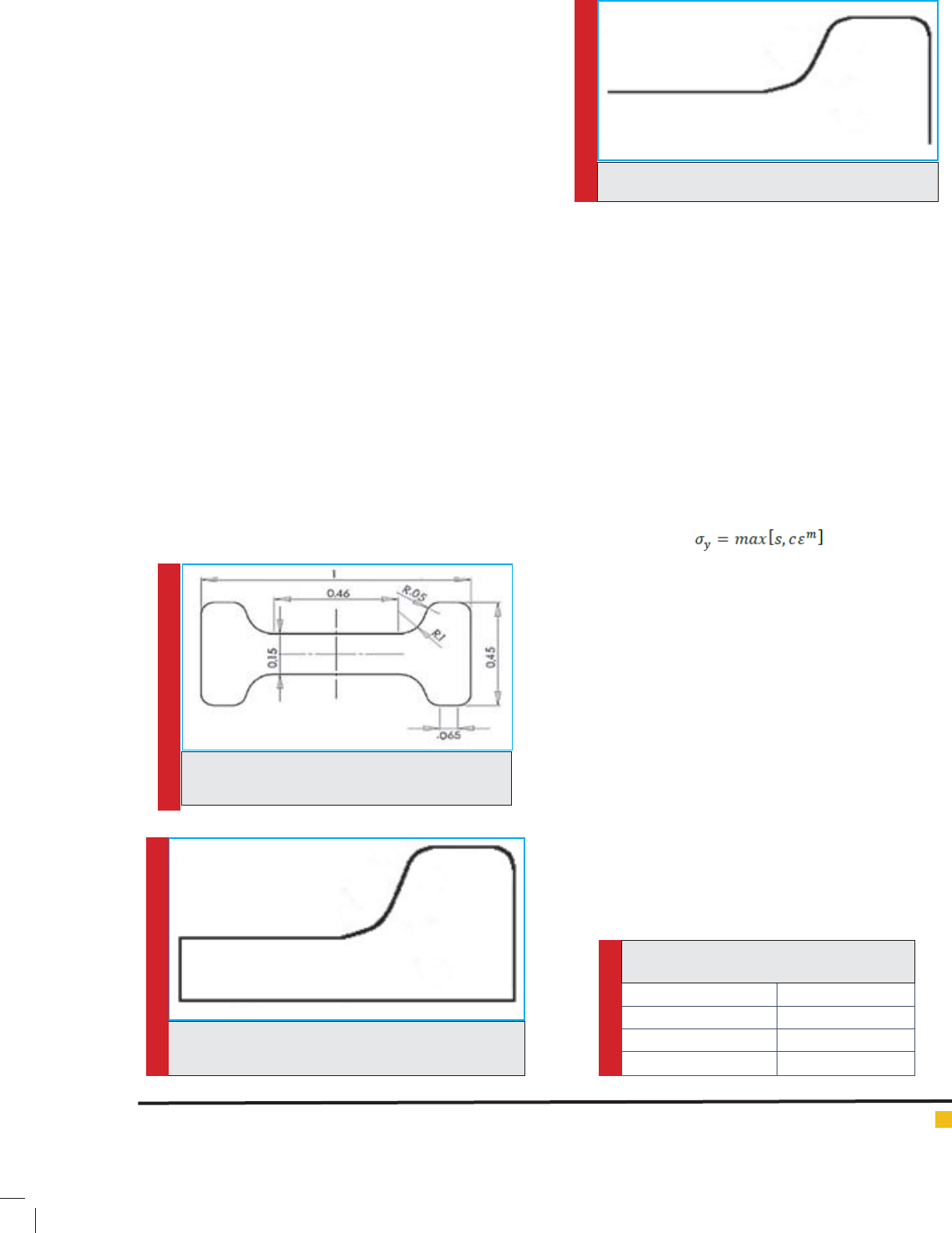
In gure 1 the assumed part is indicated with its dimen-
sions in mm. For modeling this part in ABAQUS, ¼ of
the part is considered as indicated in gure 2.
Final die shape and raw material for H-shaped part
forging
Considering the part shape, its nal die is modeled as
curve-shaped as showed in gure 3. The pre-form die for
this part is also similar to the curve-shaped nal die. Of
course, there would be a narrow path in nal die for bet-
ter material ux and the extra materials are extracted as
pleated one. The raw part is considered for a cylindrical
die with height of 0.9 m and radius of 0.3 m. since the
raw part is axisymmetric, for its modeling ¼ of the part
is used which is rectangular with height of 450 mm and
width of 300 mm.
Raw material physical properties
AL2014 is selected as raw material. Since, forging
processes are performed in high temperature (400° C),
the elastic and plastic properties of this aluminum are
required in high temperature. These properties are (Altan
et al. 1983):
- Primary yield stress=23.7 MPa
- Poisson’s coef cient= 0.33
- Elasticity module=27.8 GPa
- Stress-strain relationship in plastic state
(1)
In this equation, s is the primary yield stress, c is the
ow constant and m is the strain-rate hardening which
are c=1.02e8 MPa and m=0.11 for aluminum at 400° C.
2.2.4 The required pre-form phases’ number
In forging, at rst the required number of pre-form
phases’ has to be determined. For this purpose, one can
make use of trial and error method or proposed meth-
ods in the previous articles. In this research, considering
the H-shaped part for forging, in order to determine the
pre-form phases’ number, the Thomas’ method is used.
Considering the part’s height-width ratio, the number of
phases required is listed in Table 1.
Considering the part’s dimensions used in this
research, only one pre-form phase is needed. For this
reason, the part forging includes 2 stages. At the rst
phase, pre-form and in the second stage the nal die
would be applied.
FIGURE 1. H-Shaped part geometry (Abri Nia
et al. 2006)
FIGURE 2. Part required geometry for modeling in
ABAQUS
FIGURE 3. Die’s nal shape
Table 1. Number of required pre-forms
based on height-width ratio
height-width ratiorequired pre-forms
0-2No need to pre-form
2-31 pre-form phase
3 and more2 pre-form phases
BIOSCIENCE BIOTECHNOLOGY RESEARCH COMMUNICATIONS FORGING PRE-FORM DIES OPTIMIZATION USING ARTIFICIAL NEURAL NETWORKS 77
Hashemzadeh, Eftekhari and Loh-Mousavi
2.2.5 Mathematical function used for the H-shaped
part’s pre-form
The pre-form’s geometry is estimated from mathematical
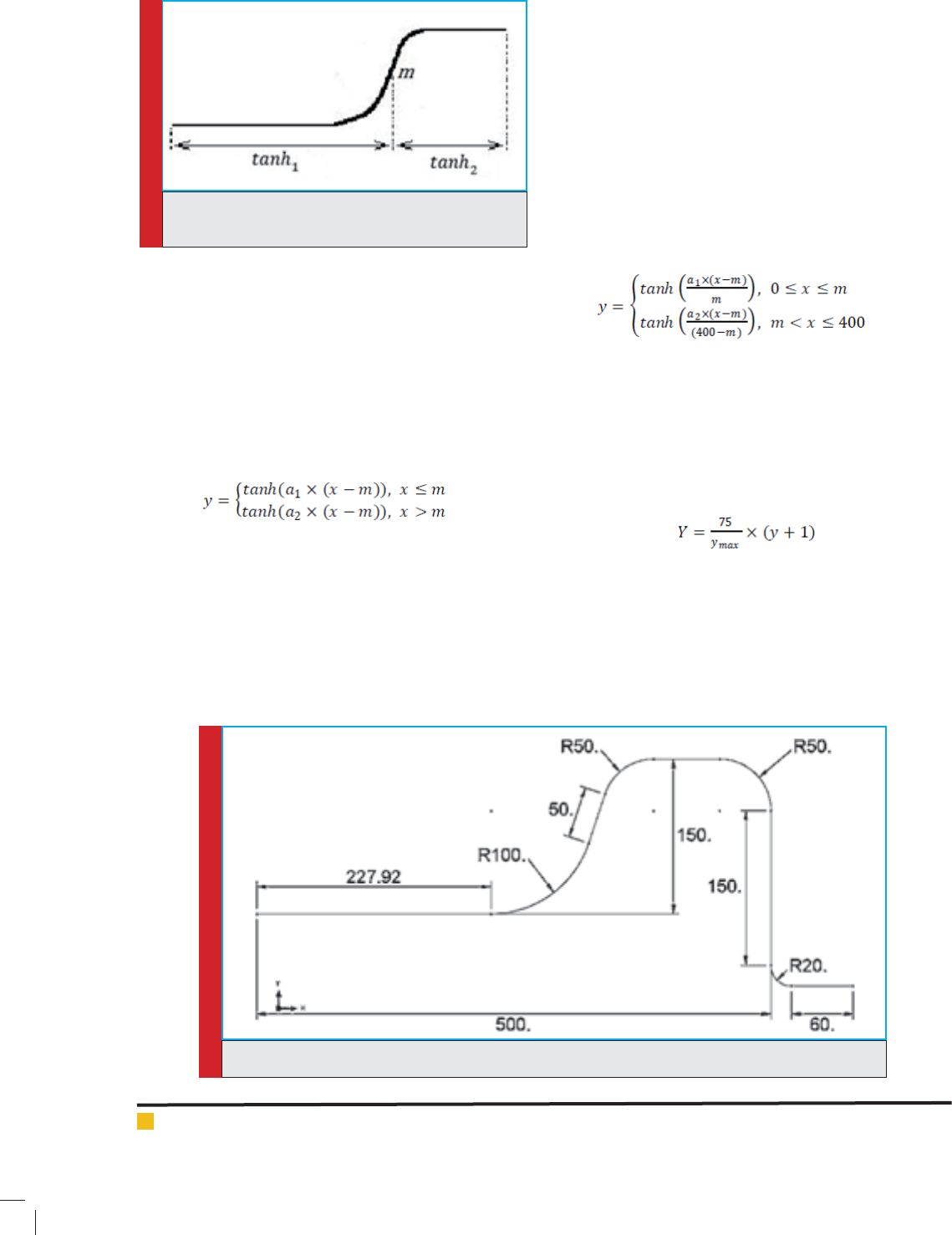
functions and the nal die shape. Figure 4 demonstrates
the mathematical functions used for pre-form die shape
estimation. This curved-shape consists of 2 tangent
hyperbolic functions interconnected in point m.
Equation 2 expresses the combination of these 2
functions as a new function.
(2)
In this relation, x is the pre-form die’s width coordinate,
y is the pre-form die’s height coordinate before mapping,
a
1
and a
2
are hyperbolic tangent functions’ coef cients
and m is the interconnection point of both functions.
The pre-form die’s dimensions are selected accord-
ing with the nal part shape and primary part shape.
Considering that the part forging process has one
pre-form phase, the pre-form die shape is consid-
ered a middle shape between nal part and primary
part’s shapes. The curve width formed by equation 2
is selected between the primary part’s width (300 mm)
and the nal part’s width (500 mm) which would be
400 mm. also, change of its height equals half of the
nal part’s height change (150 mm). As a result, the
pre-form die height would be 75 mm. therefore, the die
width and height intervals would be [0, 400] and [0, 75]
respectively. Relations 3 indicates the function used in
equation 2 which is mapped in to the required width
interval.
(3)
In equation 3, x is the pre-form die width coordinate; y
is the pre-form die height coordinate before mapping,
a
1
and a
2
are hyperbolic tangent functions coef cients
and m is interconnection point of both functions. Rela-
tions 4 indicates the function used in equation 3 which
is mapped to the required width interval. This equation
is the nal problem relation.
(4)
In this equation, y is the pre-form die height coordinates
before mapping, Y is the pre-form die height coordinate
after mapping and y
max
is a point of pre-form die with
highest height.
FIGURE 4. Die’s shape estimation by mathematical
functions
FIGURE 5. Finaldiegeometry
78 FORGING PRE-FORM DIES OPTIMIZATION USING ARTIFICIAL NEURAL NETWORKS BIOSCIENCE BIOTECHNOLOGY RESEARCH COMMUNICATIONS
Hashemzadeh, Eftekhari and Loh-Mousavi
RESULTS AND DISCUSSION
FINITE ELEMENTS SIMULATION AND RESULTS
OF FORGING
Required parts formation
The parts required for forging process simulation are raw
part, pre-form die and the nal die which are modeled in
part setting of ABAQUS. All three parts are modeled in
axisymmetric form.
In case of pre-form die, the part is modeled in ana-
lytic rigid type and wire-shaped. The raw part which is
modeled from deformable type and shell-shaped one. In
case of nal die, similar to pre-form die, the modeling
was analytic rigid type and wire-shaped. The nal die
geometry is indicated in gure 5.
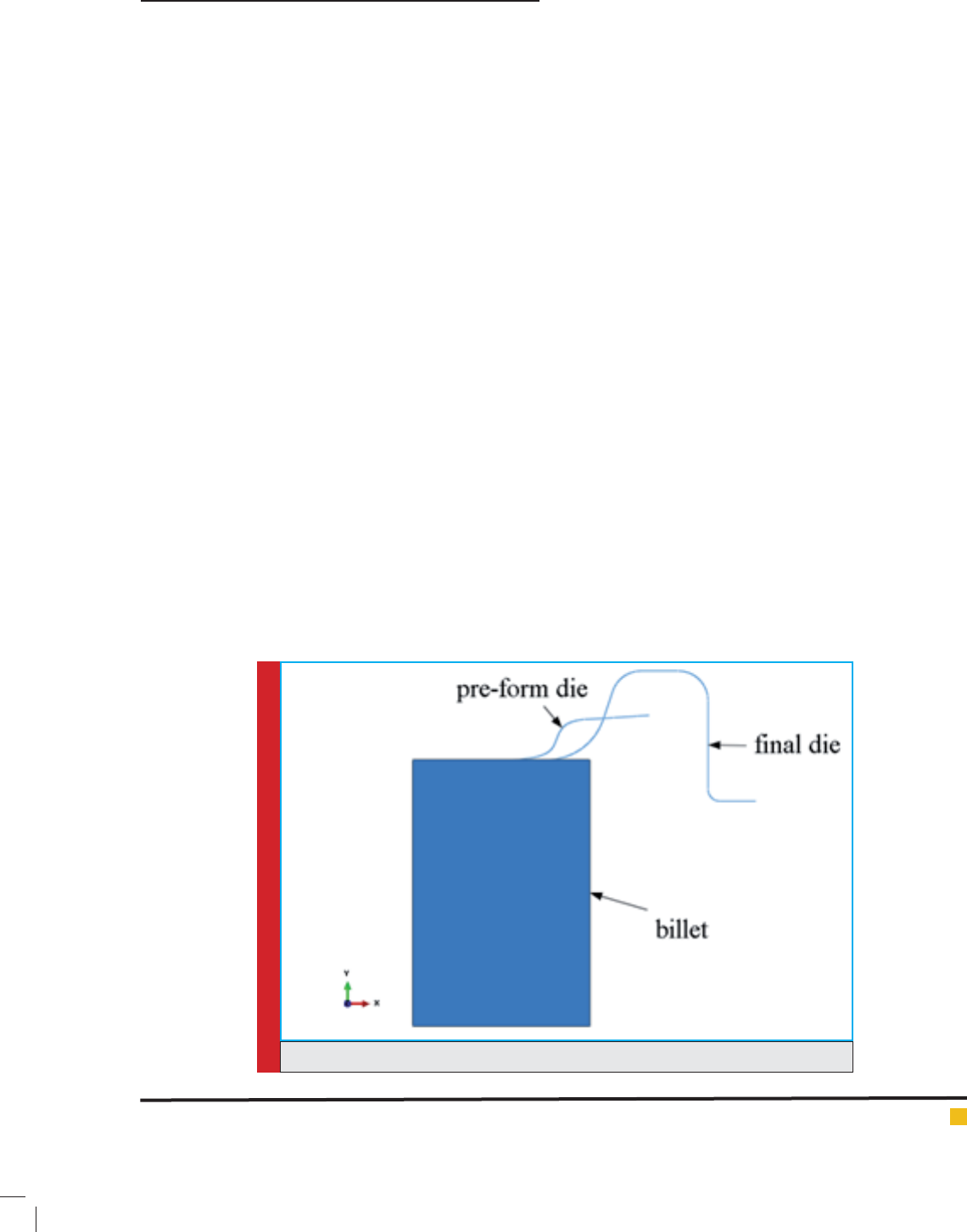
Parts assembly
For parts assembling, the left end of pre-form and nal
die is places on the top surface of the raw part. Figure 6
indicates the parts assemble.
Loading and boundary conditions de nition
In this subsection, motion and the loading as well as
parts boundary conditions are determined. In this pro-
cess, loading condition is applied in the form of die dis-
placement. In the rst phase, the pre-form die moves
down 187.5 mm and in the second phase the nal die
moves down 375 mm. The die’s motion type is also
selected as smooth step.
In case of boundary conditions, for all motion steps,
the axis line of the raw part is in horizontal direction
and its rotation is about the vertical axis on the surface.
The down surface of the raw part is also xed in the
vertical direction.
Part meshing
This section deals with the suitable meshing in order
to solve the problem. The pre-form and nal dies need
no elements due to their nal selection as rigid body
and the only raw material needs meshing. Element type
for raw part is CAX4R. This element is of quadrilateral
axisymmetric and 4-node type reduced by integration.
The suf cient elements number for part meshing is
selected as 2128 to reach convergence.
Problem solving results demonstration
In this research, in order to nd lling percentage, the
Photoshop software is used. For this reason, at rst the
simulation result obtained from the ABAQUS with format
of PNG is stored with the resolution of 1056×453 pixels.
Then, the PNG le is loaded in Photoshop and the pleated
zone is removed and using its analysis tool, the num-
ber of pixels for the nal part is calculated. Comparing
this number of pixels with the nal die pixels number in
completely lled state, the lling percentage of the die
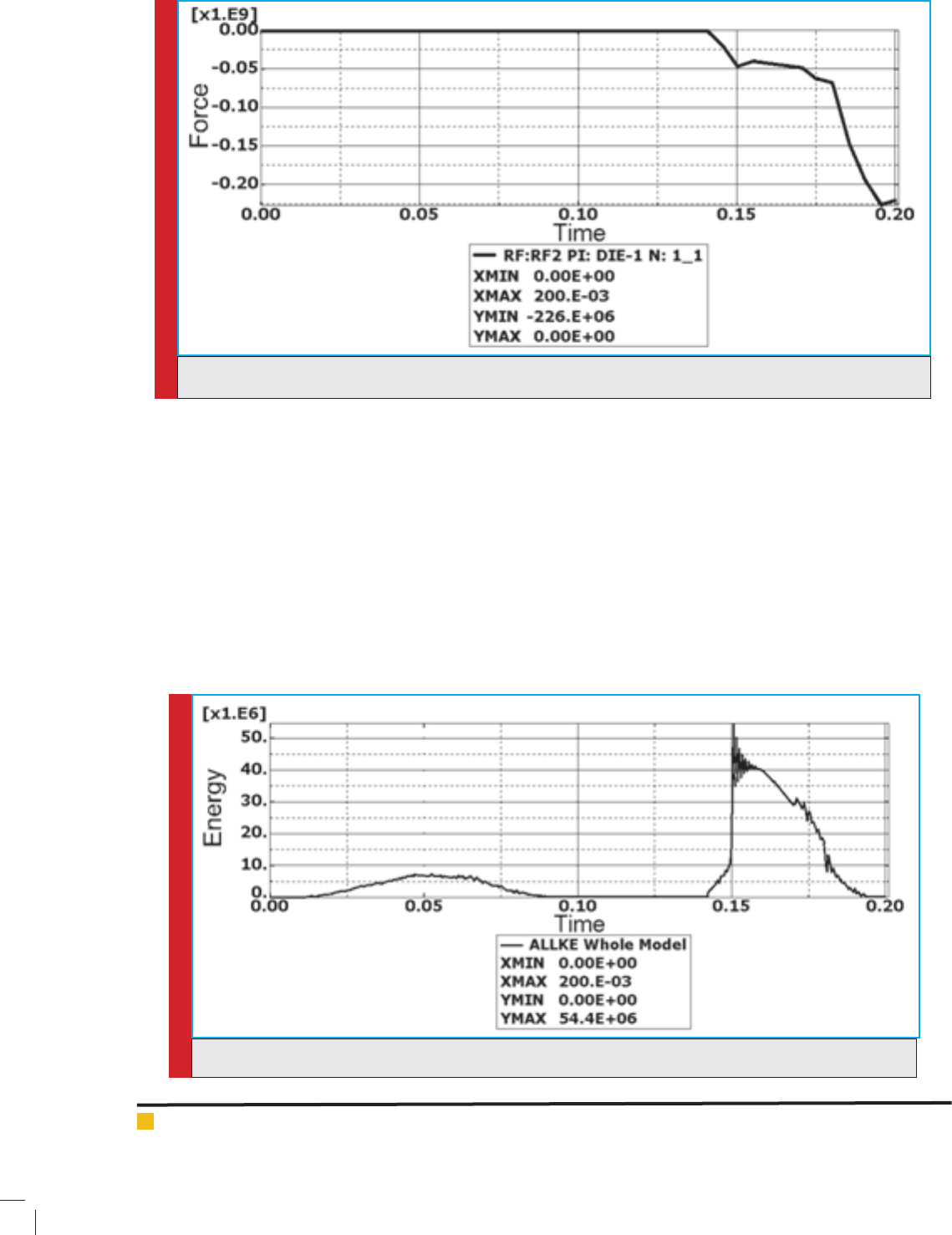
is obtained. The next parameter obtained from simula-
tion is the maximum force required for forging. As it is
seen in gure 7, plotting the diagram of exerted force on
the nal die against time, one can obtain this maximum
force. Maximum force required for this model is 226 MN.
Simulation validating
In order to validate simulation and results, several check
points are implied as follows.
FIGURE 6. Parts assemble
BIOSCIENCE BIOTECHNOLOGY RESEARCH COMMUNICATIONS FORGING PRE-FORM DIES OPTIMIZATION USING ARTIFICIAL NEURAL NETWORKS 79
Hashemzadeh, Eftekhari and Loh-Mousavi
FIGURE 7. Force diagram against time for nal die
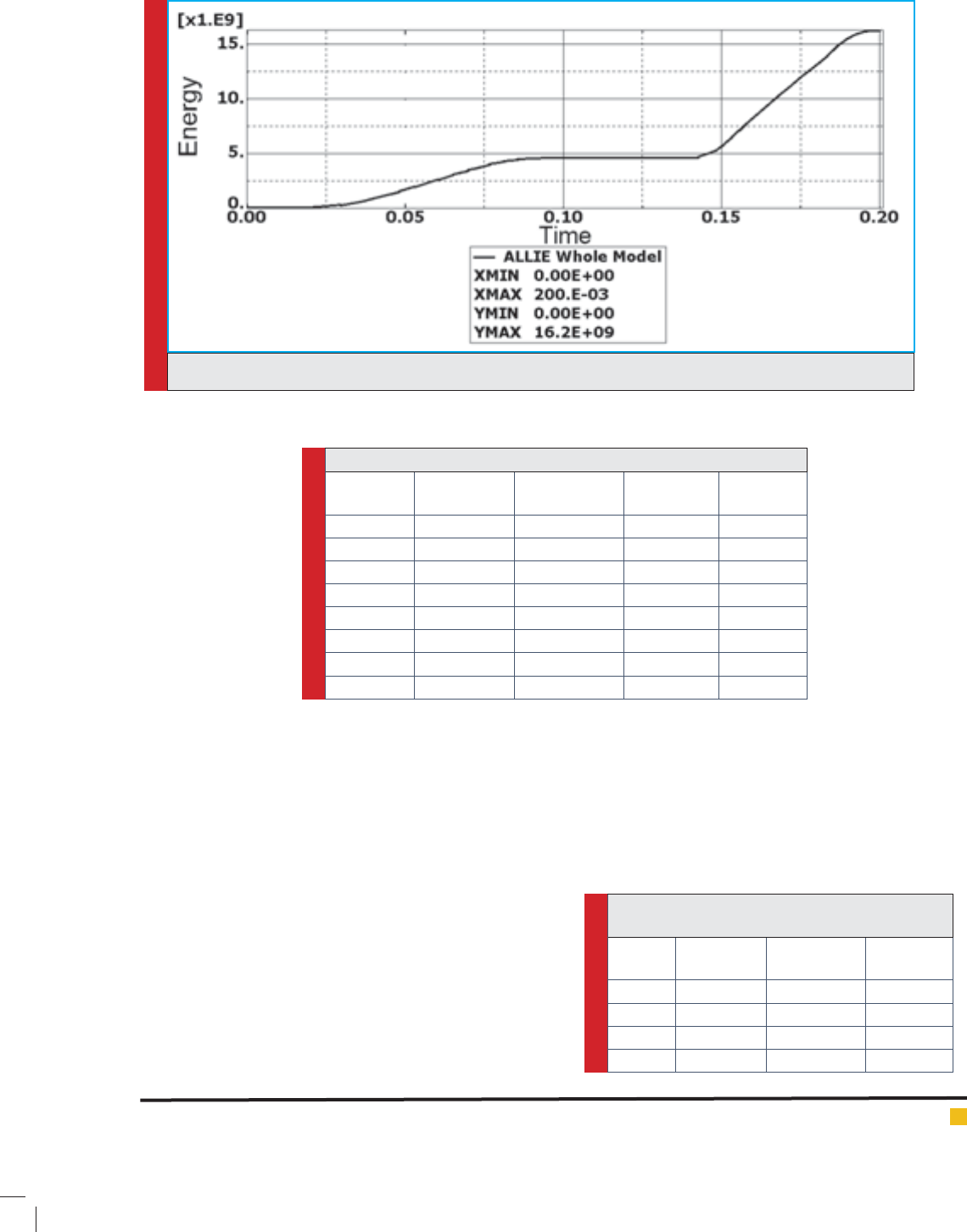
FIGURE 8. Kinetic energy diagram during process
Kinetic energy-internal energy ratio
In cases the mass scale method is used for problem solv-
ing, the energy ratio should be validated. For validating,
the maximum kinetic energy-maximum internal energy
ratio is used. The value of this proportion should not be
more than 0.1. This means that the maximum kinetic
energy is 10% of the maximum internal energy. Figure
8 represents the kinetic energy and gure 9 shows inter-
nal energy diagram against time. These diagrams can be
helpful in calculating the maximum kinetic and internal
energy.
As it is observed from gures 8 and 9, the maximum
kinetic energy value is 54.4 MN/m and maximum inter-
nal energy value is 16.2 GN/m. the ratio of these ener-
gies is about 0.34% which is acceptable.
Evaluation of elements’ number and results convergence
Making use of suf cient elements in order to make sure
the solutions’ validity is of signi cant importance. Lower
elements than the necessary level causes wrong solu-
tions. Following, if the elements’ number be more than
the necessary level, this would not cause large changes
80 FORGING PRE-FORM DIES OPTIMIZATION USING ARTIFICIAL NEURAL NETWORKS BIOSCIENCE BIOTECHNOLOGY RESEARCH COMMUNICATIONS
Hashemzadeh, Eftekhari and Loh-Mousavi
in the solution and only takes more time to solve the
problem which is costly. Here, for validating the simula-
tion, the necessary results of the problem for 8 different
number of elements are calculated and the results are
listed in table 2.
As it is seen from the above table, the output param-
eters change signi cantly up to 2128 elements and after
that the changes are negligible.
3.1.6.3 Step time
The considered time for solving the problem in step
module is effective on the problem results. If the time
considered be very low, then the results would be wrong
and if the time was very high, then the software would
require more time for problem solving which leads an
increase in problem processing time.
Table 3 lists the results obtained from applying differ-
ent times in step module. As it is seen from results, 0.1
s seems suf cient.
It is important to note that due to the fact that the
process is isothermal and material properties are consid-
ered independent of temperature and strain rate, the step
FIGURE 9. Internal energy diagram during process
Table 2. Simulation results for different number of elements
Processing
time (s)
Maximum
force (MN)
Maximum
plastic strain
Die lling
percentage
Elements
number
11.41343.13097.75150
60.501795.14598.61600
114.71905.48498.94950
166.42087.52598.881350
139.72177.33699.101734
306.622610.31699.362128
358.02249.25399.082301
385.322311.48999.142400
Table 3. Simulation results by applying different
step times
Maximum
force (MN)
Maximum
plastic strain
Die lling
percentage
Step
time (s)
22210.56699.310.05
22111.25799.130.07
22610.31699.360.10
22010.83799.970.12
BIOSCIENCE BIOTECHNOLOGY RESEARCH COMMUNICATIONS FORGING PRE-FORM DIES OPTIMIZATION USING ARTIFICIAL NEURAL NETWORKS 81
Hashemzadeh, Eftekhari and Loh-Mousavi
time doesn’t signi cantly affect the output parameters
dramatically.
Finding an optimal pre-form die using ANN and
continuous GA
Designing an Arti cial Neural Network
Since the FEM simulation is very time consuming, an
ANN is used to estimate the forging process results for
different settings. A multilayer feed forward Percep-
tron network is chosen for this reason and the forging
process input and output data are used for learning the
network parameters. The network parameters include
weights and biases which should be adjusted in such a
way to optimize the network performance. The network
performance is considered the minimum error between
network outputs and targets. In order to optimize, one
must de ne a performance index. In this research, mean
square error is used as a performance index. MSE is
the most common and desirable error function used for
multi-layer networks.
Transfer functions selection
Transfer functions are determined based on the require-
ments of a problem. Considering recent studies and
researches for correct results prediction from network as
well as making use of the back propagation method in
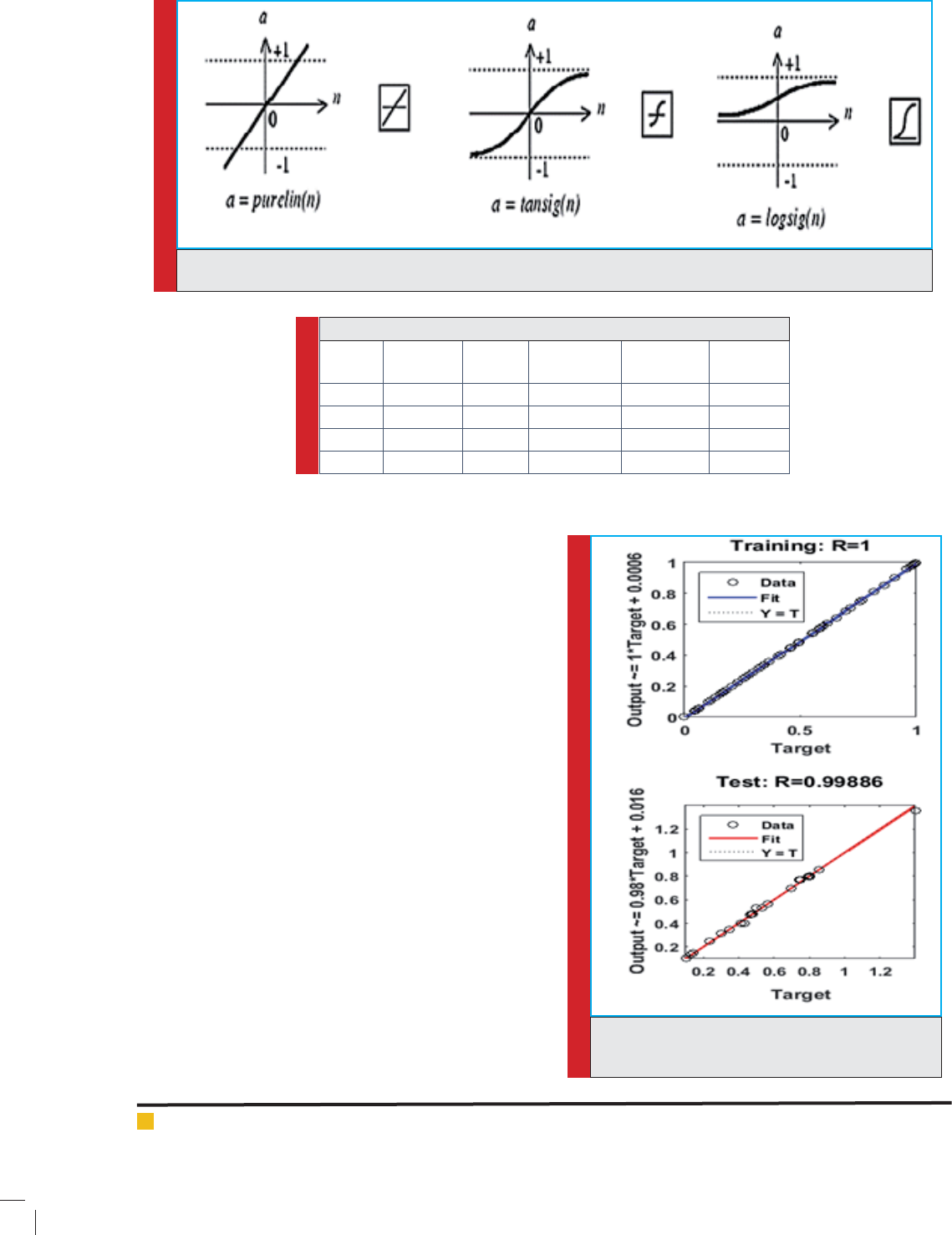
FIGURE 10. Widely used transfer functions in NN (Kia, 2010)
Table 4. Results obtained from networks run with different topologies
Maximum
error
Minimum
error
Correlation
coef cient
MSETopologySerial
0.47-0.330.870.00895,12,31
0.35-0.140.970.002312,15,32
0.10-0.210.940.0002118,12,33
0.05-0.030.990.0000520,40,34
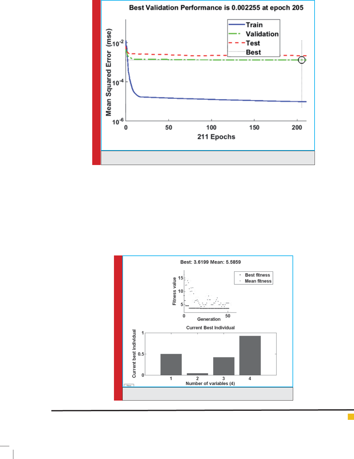
FIGURE 11. Test and training correlation coef cient
diagram fortrained network
82 FORGING PRE-FORM DIES OPTIMIZATION USING ARTIFICIAL NEURAL NETWORKS BIOSCIENCE BIOTECHNOLOGY RESEARCH COMMUNICATIONS
Hashemzadeh, Eftekhari and Loh-Mousavi
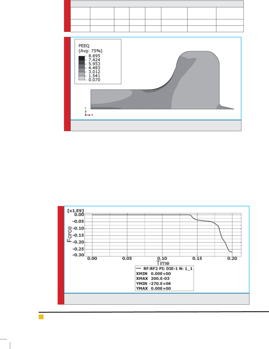
FIGURE 12. Network performance diagram
FIGURE 13. Fitness convergence and best generation in normal form
this research, the only requirement for these functions is
that they have to be differentiable in the whole domain,
since their differential is used in the learning process.
Among most applicable functions, the sigmoid and lin-
ear functions are used widely. Figure 10 indicates some
of these functions.
In this research, the sigmoid hyperbolic tangent func-
tions in network hidden layers and the linear transfer
function in last layer are used.
ANN Optimal topology
In this section, several neural networks are designed with
different topologies. Then, these networks are trained
and on the basis of performance index, the optimal net-
work is selected for this research. Of course, for training
the network, all data has to be normalized.
BIOSCIENCE BIOTECHNOLOGY RESEARCH COMMUNICATIONS FORGING PRE-FORM DIES OPTIMIZATION USING ARTIFICIAL NEURAL NETWORKS 83
Hashemzadeh, Eftekhari and Loh-Mousavi
Table 5. Results obtained from normal and real scale
Maximum
force (MN)
Maximum
plastic strain
Die lling
percentage
a2a1m
Raw part’s
width
Scale
0.170770.30381.030.92140.42140.04810.5Normal
2718.887100.0613.99.6205.8302.5Real
FIGURE 15. Diagram of force exerted on the nal die for optimal state
FIGURE 14. Plastic strain contour related to optimal state
Optimal network selection
Table 4 lists the results obtained from network run for
several different topologies. In this table, the numbers in
the topology column de nes the number of neurons in
different layers. As it is seen, the last network with three
layers containing 20 and 40 neurons in the hidden lay-
ers has the best MSE and correlation coef cient.
Figure 11 indicates the correlation coef cient for
training and test data and gure 12 indicates the net-
work performance.
These gures show the chosen network capabili-
ties, so this network would be used to simulate the
forging process as a tness function in optimization
using GA.
3.2.5 The optimal pre-form die obtained by continuous
GA
Figure 13 indicates the tness convergence diagram and
the best generation diagram. It is notable that to make
sure the GA results are global minimum, the optimiza-
84 FORGING PRE-FORM DIES OPTIMIZATION USING ARTIFICIAL NEURAL NETWORKS BIOSCIENCE BIOTECHNOLOGY RESEARCH COMMUNICATIONS
Hashemzadeh, Eftekhari and Loh-Mousavi
tic strain contour and gure 15 indicates the exerted
force on the nal die.
Table 6 lists the results of the optimal pre-form die
nite element simulation in comparison with the results
obtained from the GA. As it is observable from the
results, there is very small difference between NN results
and ABAQUS results. This means that NN is designed
well and can predict the process as well.
To ensure the obtained result is the optimum state of
the pre-form die, several random states were simulated
and their FEM results are shown in the Table 7 in compar-
ison to best result obtained by the GA method. This table
proofs the optimality of GA results versus other states.
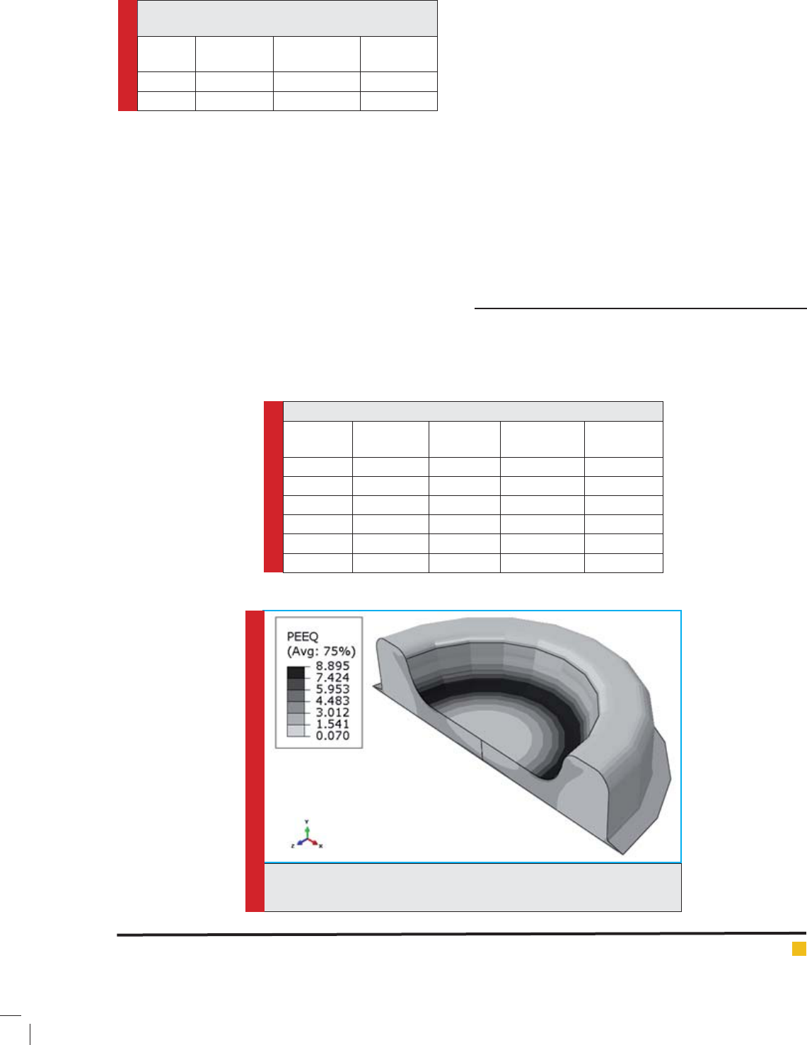
In gure 16, the cut section of the optimal state of the
part is represented at the end of the nal die application.
CONCLUSION
In this paper, necessity of using pre-form dies in forg-
ing process declared and pre-form die designing methods
were studied. Following, the GA capabilities were out-
Table 7. Comparison of GA result and ve random states
Maximum
force (MN)
Maximum
plastic strain
Die lling
percentage
Raw part’s
width
state
22310.25499.18300Random 1
2109.98598.91301Random 2
52413.83499.89302.5Random 3
53013.779100305Random 4
52813.51099.16304Random 5
2708.89599.96302.5best
Table 6. Comparison between nite elements and GA
results
Maximum
force (MN)
Maximum
plastic strain
Die lling
percentage
Results
2708.89599.96ABAQUS
2718.887100.06GA
FIGURE 16. Cut section of part for optimal state at the end of nal die
application
tion process using GA is iterated 20 times and the best
result is considered so that its validity was assured.
Following, the best generation values are substituted
in neural network and its results were extracted. The
results obtained were in normal state; therefore, param-
eters values returned to their primary scale. Table 5 lists
the results obtained in normal and real scale.
3.2.6 Optimal pre-form die nite element simulation
and results comparison
Using the optimized parameters obtained from the GA
method, the forging process is simulated in ABAQUS and
the results obtained would be compared to the results
obtained from the GA. Figure 14 demonstrates the plas-
BIOSCIENCE BIOTECHNOLOGY RESEARCH COMMUNICATIONS FORGING PRE-FORM DIES OPTIMIZATION USING ARTIFICIAL NEURAL NETWORKS 85

Hashemzadeh, Eftekhari and Loh-Mousavi
lined such as their application on continuous problems
optimization. It was indicated how to make use of math-
ematical functions in GA. Following, a new method for
designing the optimal pre-form dies was proposed. In this
method, without simplifying the pre-form die shape and
only using different mathematical functions combina-
tion, the optimal pre-form die shape was designed. To this
end, after selecting the suitable function for pre-form die
shape, several random pre-form die shapes were produced
and then using nite elements model and ABAQUS soft-
ware, the pre-form die forging process was simulated and
results were extracted. These results were used for train-
ing the ANN, a network which can predict the forging
process performed in nite elements model due to its time
consumption. Finally, using designed ANN and effective
parameters on forging, the target function required for
GA was formed and following the algorithm running, the
optimal pre-form die was obtained. This method was used
for an H-shaped part which was axisymmetric to evalu-
ate its performance. The results show that combination of
ANN and GA makes a powerful tool for designing com-
plex pre-form dies. Here, the method was used for a part
which needs only one step pre-form die, and may be used
for more complex parts with several pre-form dies to vali-
date its potential. Also the method can be extended using
more parameters including number of pre-form dies, ux
stress, friction coef cient and so on. Finally comparison
of theoretical optimized results with experimental data is
suggested.
REFERENCES
Abri Nia K., M.H. Naie, Y. Taqi Put Lahijani, (2006): Pre-form
Forging Cast Design in Reverse Transformation and Finite Ele-
ments Method, Technical college magazine, Vol 40, pp 763-
769.
Altan T., G. Ngail, G. Shen, M.H. Hojati, (2006): fundamentals
of cold and hot forging, Mazandaran University Publication,
Babolsar.
Altan T., S. I. Oh, H. L. (1983): Gegel, Metal Forming: Funda-
mentals and Applications, American Society for Metal, Metals
Park.
Bonte M. H. A., L. Fourment, T. T. Do, A. H. Van Den Boogaard,
J. Huétink, (2010): Optimization of forging processes using
Finite Element simulations Structural and Multidisciplinary
Optimization, Structural and Multidisciplinary Optimization,
Vol 42, Issue 5, pp 797-810.
Grandhi R. V., H. Cheng, S. S. Kumar, (1993): Optimum Design
of Forging Process with Deformation and Temperature Con-
straints, ASME Advances in Design Automation, Vol 2, pp
583-593.
Hosseinzadeh M., M. Bakhshi-Jooybari, M. Shakeri, H. Mosta-
jeran, H. Gorji, (2010): Application of Taguchi Method in Opti-
mization of New Hydroforming Die Design, Steel Research
International, Vol 81, Issue 9, pp 647-650.
Khalili K., Fonoudi H., (2010): Simulation of Hot Forging Pro-
cess Using FEM and ANN Method to Predict Metal Forming
Parameters, the 12th Iranian Conference on Manufactoring
Engineering, SMEI University of Tehran, Iran.
Khalili K., P. Kahal, S. Eftekhari, M. S. Khalili, (2011): Blank
Optimization in Elliptical-shape Sheet Metal Forming Using
Response Surface Model Coupled with Reduced Basis and Finite
Element Analysis, Key Engineering Materials, Vol 473, pp 683.
Kia M., (2010): neural networks in MATLAB, Kian Rayaneh
Sabz publication.
Lanka S., R. Srinivasan, R. V. Grandhi, (1991): Design Approach
for Intermediate Die Shapes in Plane Strain Forgings, Journal
of Materials Technology, Vol 9, No 4, pp 193-206.
Lee S. R., Y. K. Lee, C. H. Park, (2002): A New Method of Preform
Design in Hot Forging by Using Electric Field Theory, Interna-
tional Journal of Mechanical Sciences, Vol 44, pp 773-792.
Li D.Y., Y.H. Peng, J.L. Yin, (2007): Optimization of metal-
forming process via a hybrid intelligent optimization tech-
nique, Structural and Multidisciplinary Optimization, Vol 34,
Issue 3, pp 229-241.
Lu B., H. Ou, H. Long, (2011a): Die shape optimisation for net-
shape accuracy in metal forming using direct search and local-
ised response surface methods, Structural and Multidiscipli-
nary Optimization, Vol 44, Issue 4, pp 529-545.
Lu B., H. Ou, Z.S. Cui, (2011b): Shape optimisation of preform
design for precision close-die forging, Structural and Multidis-
ciplinary Optimization, Vol 44, Issue 6, pp 785-796.
Naeemi A., (2013): Design and Optimization of Forging Pre-
form Casts in Reverse Transformation and ANN Methods, Msc.
Thesis, I.A.U, Khomeini Shahr University.
Shamsi-Sarband A., S. J. Hosseinipour, M. Bakhshi-Jooybari,
M. Shakeri, (2012): Study on the Effect of Friction Coef cient
on the Optimized Preform Die Shape in a Multistage Super-
plastic Forming.
Shamsi-Sarband A., S. J. Hosseinipour, M. Bakhshi-Jooybari,
M. Shakeri, (2013): The Effect of Geometric Parameters of
Conical Cups on the Preform Shape in Two-Stage Superplastic
Forming Process, Journal of Materials Engineering and Perfor-
mance, Vol 22, Issue 12, pp 3601-3611.
Shao Y., B. Lu, H. Ou, J. Chen, (2015): A new approach of
preform design for forging of 3D blade based on evolutionary
structural optimization, Structural and Multidisciplinary Opti-
mization, Vol 51, Issue 1, pp 199-211.
Zhao G., E.Wright, R. V. Grandhi, (1997): Sensitivity Analysis
Based Preform Die Shape Design for Net-Shape Forging, Inter-
national Journal of Machine Tools and Manufacture, Vol 37,
No 9, pp 1251-1271.
Zhao G., E.Wright, R.V. Grandhi, (1995): Forging Preform
Design with Shape Complexity Control in Simulating Back-
ward Deformation, International Journal of Machine Tools and
Manufacture, Vol 35, pp 1225-1239.
86 FORGING PRE-FORM DIES OPTIMIZATION USING ARTIFICIAL NEURAL NETWORKS BIOSCIENCE BIOTECHNOLOGY RESEARCH COMMUNICATIONS