
Enviromental behavior of steel beams embedded in
concrete under static loads
Ashkan Khoda Bandehlou
1
* and Reza Shokri Soltanabadi
2
1
Doctor Of Philosophy Of Technical Sciences, Faculty Of Engineering, Civil Engineering Department, Urmia
Branch, Islamic Azad University, Urmia, Iran
2
Ph.D. Student Of Civil Engineering-Structure, Faculty Of Engineering, Civil Engineering Department, Urmia
Branch, Islamic Azad University, Urmia, Iran
ABSTRACT
In this article environmental behavior of steel beams embedded in concrete under static loads was investigated. The
obtained experimental results were compared for precision of the sample con guration of a three-dimensional nite
element model. In this study, for modeling concrete, Concrete Damaged Plasticity was used. The analytical method used
in this study for explicit nonlinear dynamic analysis Dynamic Explicit is selected. In contrast, in samples with a ratio of
0.5 steel ange width, usually bending failure were observed.
KEY WORDS: MIXED BEAMS, FLEXURAL BEHAVIOR, STATIC LOADING, FINITE ELEMENT METHOD.
626
Technical
Communication
Biosci. Biotech. Res. Comm. 11(4): 626-633 (2018)
INTRODUCTION
Analytical studies were conducted, including the mem-
bers of the Security, by Spacone and El-Tawilin 2004. In
this study, nonlinear analysis steel-concrete composite
structures were investigated. Another study by Camps
et al., (2017) has analyzed exural behavior of composite
beams with deformable connection. How the tensions in
the interface of concrete and steel sections and increase
ductility and impact assessed concrete creep and shrink-
age behavior of the composite was investigated. Another
study evaluated the short beam strength composite col-
umns by Mirza and Skranek which was conducted in
1991. Other research studies on prestressed beams have
been combined in this research, which are based on ana-
lytically studied proposals for the design of this type of
beam bending is presented, (Zhao and Li 2017).
The survey in 1989 was conducted by Saadatmanesh
and colleagues. The use of prestressed steel beams for
composite steel - concrete increases the bearing capac-
ity of steel beams to the current stage and also increases
the resistance of the composite section nal. At the same
ARTICLE INFORMATION:
Corresponding Authors: ashkan72@rambler.ru
Received 12
th
Sep, 2018
Accepted after revision 19
rd
Nov, 2018
BBRC Print ISSN: 0974-6455
Online ISSN: 2321-4007 CODEN: USA BBRCBA
Thomson Reuters ISI ESC / Clarivate Analytics USA
Mono of Clarivate Analytics and Crossref Indexed
Journal Mono of CR
NAAS Journal Score 2018: 4.31 SJIF 2017: 4.196
© A Society of Science and Nature Publication, Bhopal India
2018. All rights reserved.
Online Contents Available at:
http//www.bbrc.in/
DOI: 10.21786/bbrc/11.4/13
Bandehlou and Soltanabadi
BIOSCIENCE BIOTECHNOLOGY RESEARCH COMMUNICATIONS ENVIROMENTAL BEHAVIOR OF STEEL BEAMS EMBEDDED IN CONCRETE UNDER STATIC LOADS 627
time prestressing tension ange reduced the amplitude
cyclic stress and improve fatigue resistance.In another
study conducted in 2005 by Ellbody and Young, shear
bond strength impact and ef ciency in composite beams
has been investigated. Another study under the title of
ultimate strength of continuous composite beams under
combined bending and cutting was done by Liang et al.
Based on numerical results, a new design model based
on vertical shear resistance and interaction Anchor -
cutting the continuous composite beams have been
proposed. The proposed design models were compared
with experimental results and good agreement is shown
(Goldston, et al. 2016 and Ongpenget al.2018).
Zhao and Li in 2008, conducted a numerical study in
conjunction with a new way to create continuity in com-
posite beams. The ow of steel beam to reduce the local
rigidity and lead to brittle fracture the concrete. In 2005,
Lam and his colleagues evaluated the behavior of shear
connectors for composite beams was conducted stud.
In this study, a model of ef cient numerical simula-
tion using the nite element method for laying out tests
have been proposed. The model was validated against
experimental results and with common standards such
as BS5950 and the information given in EC4 and AISC
were compared. By a number of researchers based on
laboratory analysis and numerical research has been
done on shear connectors, length, maximum width of
cracks in concrete was found to be reduced. Lam and
colleagues in 2005 studied pull tests on 12 samples of
pre-fabricated hollow concrete slab, the scale is com-
plete. In another work by Lam and El-Lobody (2005)
new work has been developed to FEM modeling com-
putational which has been obtained from experimental
results which have been discussed in terms of accuracy.
Comparison has been made on the conducted data and
the results show good correlation between the nite ele-
ment model from environmental point of view. In this
study, the exural behavior of steel beams embedded in
concrete under static loads is investigated for sustain-
able environmental development.
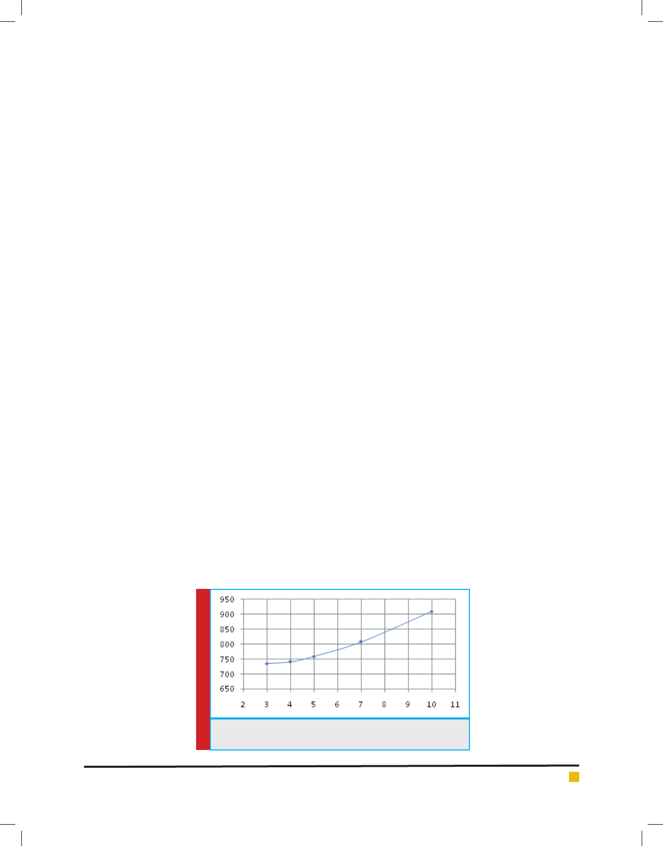
FIGURE 1. Change Chart bearing capacity by changing the size
of the mesh
STATEMENT OF THE PROBLEM
Full of strength, using techniques to enhance the capac-
ity of these members is very important. Capacity is up
against loads of material to be used simultaneously and
ef ciently.
MODELINGALMAN LIMIT FOR CONSTITUENTS
MERCURY COMPOUND
In this article for a sample con guration of a three-
dimensional nite element model is used. For concrete
modeling of three-dimensional elements (C3D8R) that
an 8-node elements with reduced integration is used.
Similar elements are considered for modeling steel sec-
tions. For longitudinal reinforcement and stirrups of the
beam elements (B31) is used.
CONCRETE IN ABAQUS FINITE ELEMENT
METHOD
In this study, the method used for modeling concrete,
Concrete Damaged Plasticity is the model. This model is
based on the assumption of isotropic damage survey and
design for use in concrete under different environmen-
talloading conditions and the desired effect was accom-
plished. The embedded model is used for reinforcement.
LOAD AND BOUNDARY CONDITIONS
In the modeling study of rigid plates with a width of 10
cm was used as loading pages. Pages load and anchor tie
in place by indicating that they have been xed. Anchor
plates on the boundary conditions with zero degrees of
freedom U1 and U2 and UR2 and UR3 have taken place.
MESHED MODEL
Analysis of each of these models were calculated. By
comparing the maximum load capacity for different
meshing, percentage differences obtained for meshing
Bandehlou and Soltanabadi
628 ENVIROMENTAL BEHAVIOR OF STEEL BEAMS EMBEDDED IN CONCRETE UNDER STATIC LOADS BIOSCIENCE BIOTECHNOLOGY RESEARCH COMMUNICATIONS
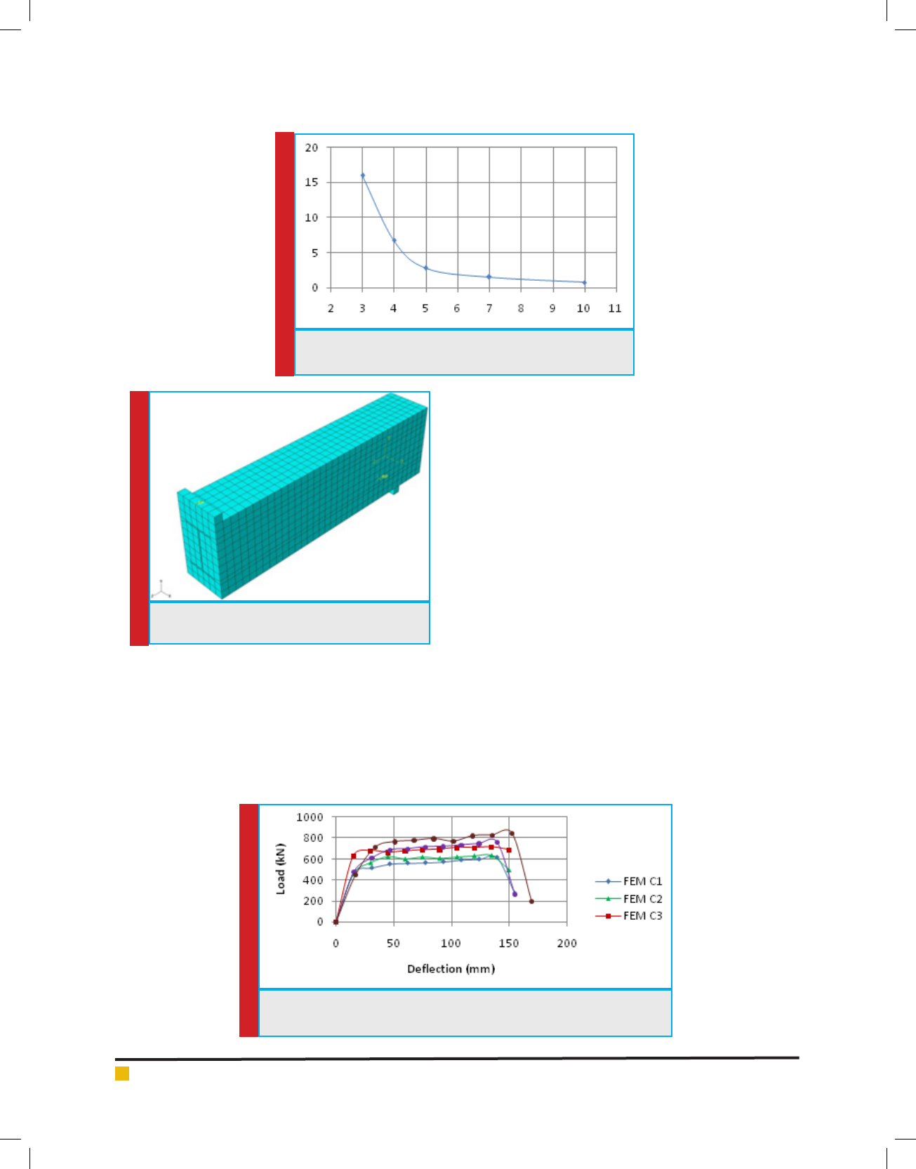
FIGURE 2. Change graph analysis time by changing the size
of the mesh
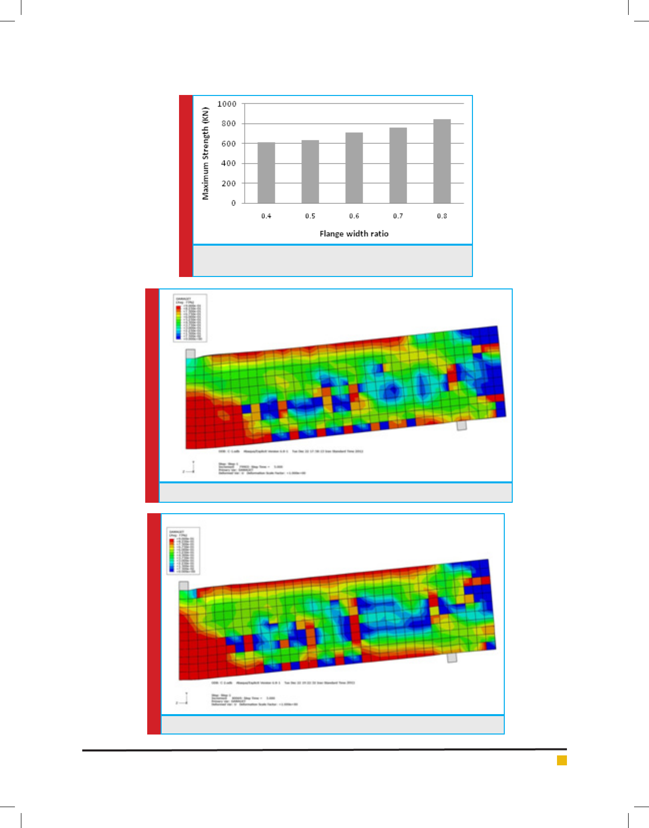
FIGURE 3. For an example of meshing in nite
element software
FIGURE 4. Bar chart - midspan displacement for models C1, C2, C3, C4 and
C5
with meshing elements smaller than 5 cm, less than 42/2
percent is obtained. That’s why the next 5 inches as the
maximum size for meshing elements have been selected.
Extrusion method used to create pieces of concrete
and steel beam is therefore for the mesh generator parts
Swept meshing techniques are used. Elements used in
the mesh of hexagonal Hex been selected. Seeded maxi-
mum size of 5 cm is selected and used to control the
curvature maximum deviation factor by default, the
software is intended to 1/0. In Figure 3 meshed model
for one of the samples shown.
ANALYSIS MODEL
Given the magnitude of the displacement and the need
for non-linear analysis, dynamic methods for the analy-
sis of selected models. The analytical method used in this
study for explicit nonlinear dynamic analysis Dynamic
Explicit is selected.
THE IMPACT OF CHANGING THE ENTIRE
WIDTH OF THE BEAM FLANGE WIDTH
STEEL TOOLS
One of the important parameters in uencing the behav-
ior of the composite beams of steel embedded in con-
crete, steel and concrete beam cross section Dimensions.
the probability of failure is compounded in July.
Is. For this purpose, ve different models, including
models with wing width ratios C1, C2, C3, C4 and C5
Bandehlou and Soltanabadi
BIOSCIENCE BIOTECHNOLOGY RESEARCH COMMUNICATIONS ENVIROMENTAL BEHAVIOR OF STEEL BEAMS EMBEDDED IN CONCRETE UNDER STATIC LOADS 629
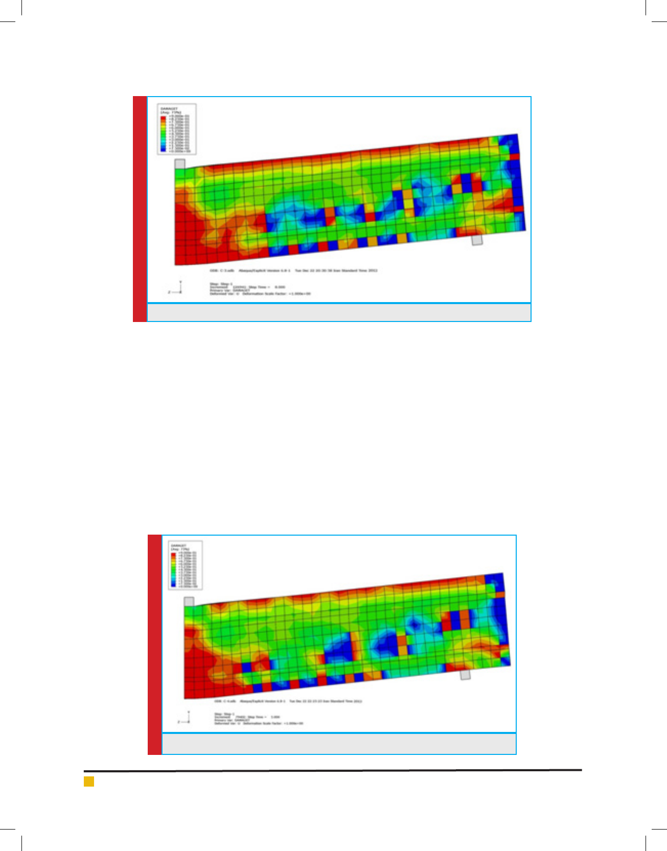
FIGURE 5. The graph ultimate bearing capacity for models C1, C2, C3,
C4 and C5
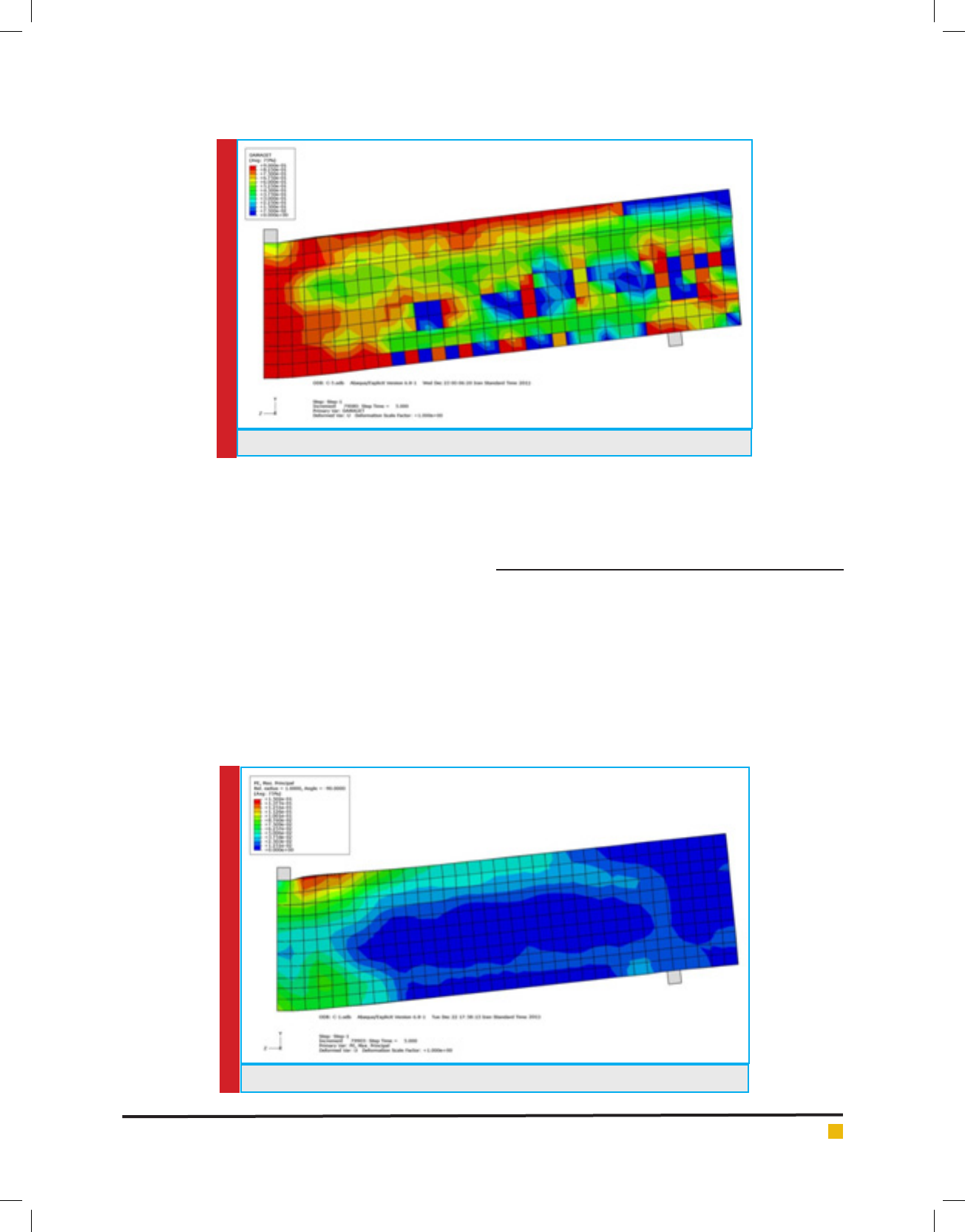
FIGURE 6. Contour stretch injury model C1
FIGURE 7. Contour stretch injury model C2
Bandehlou and Soltanabadi
630 ENVIROMENTAL BEHAVIOR OF STEEL BEAMS EMBEDDED IN CONCRETE UNDER STATIC LOADS BIOSCIENCE BIOTECHNOLOGY RESEARCH COMMUNICATIONS
FIGURE 8. Injury contour drawing model C3
FIGURE 9. Injury contour drawing model C4
respectively steel with cross-sections of 120, 150, 180,
210 and 240 cm are selected.
All models have cross-sectional dimensions of 300
× 500 mm, respectively. Longitudinal bars diameter 19
mm and diameter of 10 mm are inadequate. The distance
of each other 150 mm is considered inadequate and has
not been used in any of these models is cutting.
GRAPHS TIME – DISPLACEMENT
Bar graphs - C1 to C5 models displacement is presented in
Figure 4. As the charts once - movement can be observed
with increasing steel ange width, capacity, as well as
the nal beam forming compound has increased. Figure 5
shows the curve of the ultimate capacity models. Accord-
ing to this chart, the increase in capacity of 22.3% for
the C2 than C1 models, for models from C3 to C1 model
37/16%, 91/23% and times for the C4 to C1 model to
model C5 to C1 models from 94/37% is obtained.
TENSILE CONTOURS INJURY
In the form of (6) to (10) C1 to C5 models tensile injury
contours are provided. With a little care can be noted
that in models with smaller steel ange width, propaga-
tion of cracks at midspan is more considerable.
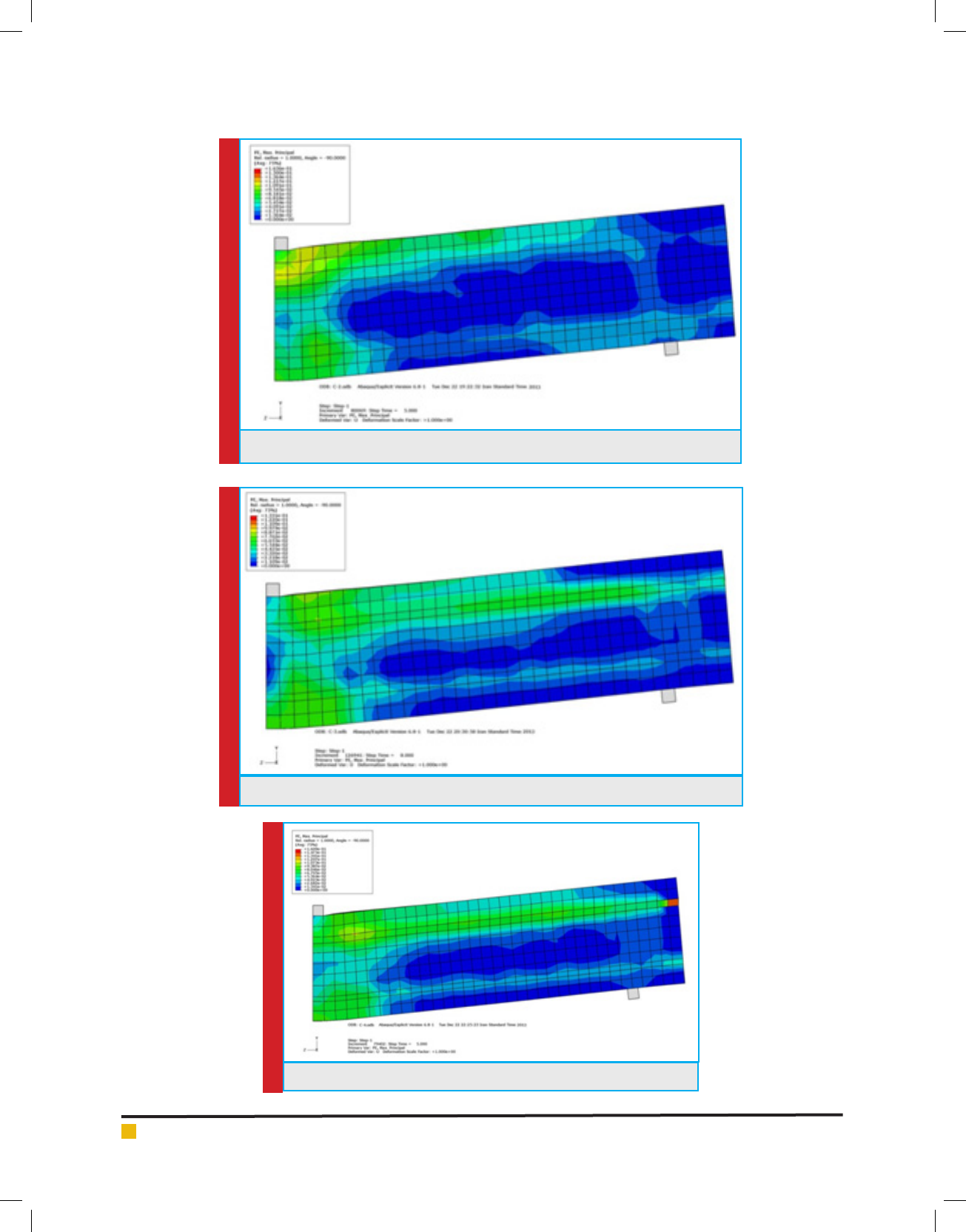
RESHAPE THE CONTOURS OF PLASTIC
Stickers (11) to (15) of plastic deformation contours C1
to C5 models for the show. three models have been pre-
dicted failure for shear.
Bandehlou and Soltanabadi
BIOSCIENCE BIOTECHNOLOGY RESEARCH COMMUNICATIONS ENVIROMENTAL BEHAVIOR OF STEEL BEAMS EMBEDDED IN CONCRETE UNDER STATIC LOADS 631
FIGURE 10. Contour injury tensile C5 model
FIGURE 11. Contour relative deformation Plastic Model C1
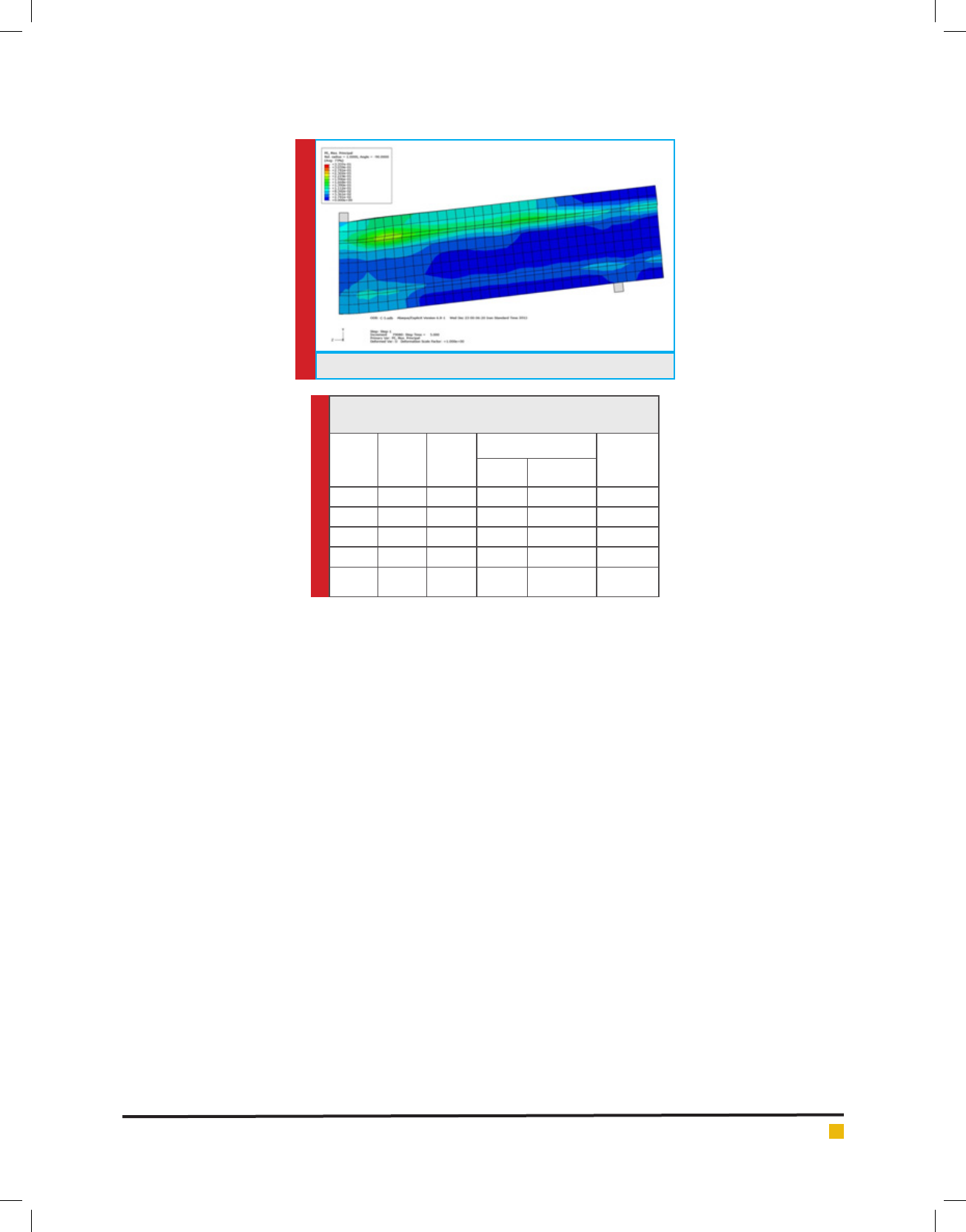
In Table 1. The results of the analysis and predic-
tion models include the strength of the type of failure is
presented. The nite element analysis results in compli-
ance with Regulation Iran relations have been evaluated.
According to a survey made very good match between
the results of nite element analysis of the samples and
relations are provided in the bylaws. The ultimate shear
capacity of 353.8 kN point in the relations of the Regu-
lations is obtained. We see that in the C1 and C2 maxi-
mum shear force obtained from nite element analysis
section is smaller than the shear capacity. Therefore,
the models are broken due to reach its ultimate exural
capacity. Finite element analysis of bending failure for
these models is the result. The results of nite element
analysis also shows shear failure for these models.
CONCLUSION
In this article Environmental behavior of steel beams
embedded in concrete under static loads were inves-
tigated. In contrast, in samples with a ratio of 0.5
steel ange width, usually bending failure have been
observed. Results demonstrated that by optimizing the
static load in the process of the production, the environ-
mental side effects will be reduced and can be ef cient
in clean concrete production.
Bandehlou and Soltanabadi
632 ENVIROMENTAL BEHAVIOR OF STEEL BEAMS EMBEDDED IN CONCRETE UNDER STATIC LOADS BIOSCIENCE BIOTECHNOLOGY RESEARCH COMMUNICATIONS
FIGURE 13. Contour relative deformation Plastic Model C3
FIGURE 14. Contour relative deformation Plastic Model C4
FIGURE 12. Contour relative deformation Plastic Model C2
Bandehlou and Soltanabadi
BIOSCIENCE BIOTECHNOLOGY RESEARCH COMMUNICATIONS ENVIROMENTAL BEHAVIOR OF STEEL BEAMS EMBEDDED IN CONCRETE UNDER STATIC LOADS 633
FIGURE 15. Contour relative deformation Plastic Model C5
Table 1. resistance and failure mode of composite beams
with steel ange width ratios of
Model
Width
steel
Width
ratio
Resistance models
The
type of
fracture
V (KN) M (KN m)
C1 120 0.4 306.5 459.8 Bending
C2 150 0.5 316.4 474.6 Bending
C3 180 0.6 356.7 535.1 Bending
C4 210 0.7 379.8 569.7 Bending
C5 240 0.8 422.8 634.2 Bending
REFERENCES
Camps, B.; Baktheer, A.; Hegger, J.; Chudoba, R (2018). Experi-
mental Characterization of Bond Fatigue Using Beam-End
Tests with Push-In Loading. Proceedings 2, 417.
Ellobody, E. and Young, B. (2005) Performance of shear con-
nection in composite beams with pro led steel sheeting,”
Department of Structural Engineering, Faculty of Engineering,
Tanta University, Tanta, Egypt, Journal of Hydraulic Engineer-
ing, ASCE, Vol.132, No. 9, pp.971-982
Goldston, Matt & Remennikov, Alex & Sheikh, Md. (2016).
Experimental Investigation of the Behaviour of Concrete
Beams Reinforced with GFRP Bars under Static and Impact
Loading. Engineering Structures. 113. 220-232. 10.1016/j.eng-
struct.2016.01.044.
Lam, D., El-Lobody, E. (2005) Behavior of Headed Stud Shear
Connectors in Composite Beam School of Civil Engineering,
University of Leeds, U.K., Journal of StructuralEngineering,
Vol.131, No.1, pp. 96-107, 2005.
Liang, Q.Q., Uy, B., Bradford, A., and Ronagh, H.R. (2003) Ulti-
mate strength of continuous composite beams in combined
bending and shear, School of Civil and Environmental Engi-
neering, The University of New South Wales, Sydney, Australia,
Journal of Structural Engineering, Vol.131, No.10, pp.1593-1600
Mirza, S.A., Skrabek, B.W. (1991) Reliability of Short Com-
posite Beam-Column Strength Interaction,” Department of
Civil Engineering, University of Lakehead, Canada, Journal of
Structural Engineering, Vol.117, No.8, pp.2320-2339
Nardin, S.D., El Debs, L.H.C. (2009) Study of partially encased
composite beams with innovative position of stud bolts,
Department of Structural Engineering, University of Sao Paulo
at Sao Carlos, Sao Carlos, Brazil, Journal of Constructional
Steel Research, Vol.65, No.2, pp.342-350
Ongpeng, J. M. C., Oreta, A. W. C., & Hirose, S. (2018). Inves-
tigation on the Sensitivity of Ultrasonic Test Applied to Rein-
forced Concrete Beams Using Neural Network. Applied Sci-
ences, 8(3), 405.
Saadatmanesh, H., Albrecht, P., Ayyub, B.M. (1989) Guide-
lines for Flexural Design of Prestressed Composite Beams
Civil. Engrg.andEngrg. Mech., University of Arizona, Jour-
nal of Structural Engineering, Vol.115, No.11, pp.2944-
2961
Spacone, E., El-Tawil, S. (2004) Nonlinear Analysis of Steel-
Concrete Composite Structures Department of Civil Engineer-
ing, Department of Civil Engineering, University of Colorado,
Journal of Structural Engineering, Vol.31, No.2, pp.523-533,
2004.
Zhao, G., Li, A. (2017) Numerical study of a bonded steel and
concrete composite beam Laboratory of Mechanics, Materi-
als and Structures, University of Reims Champagne Ardenne,
France, Journal of Structural Engineering, Vol.86, No.19-20,
pp.1830-